
The most important rule in overmolding design guidelines is to design the interface first. The bond line—the surface where the rigid substrate meets the soft overmold—decides whether the part holds together, seals correctly, and looks clean. Wall thickness, shut-off, gate location, and shrinkage all exist to protect that interface. Get them right and yield stays high; get them wrong and you see peeling, flash, sink marks, or warping. The guidance below applies typical values that should be confirmed against the specific resin grade and tool before production.
These rules are the design layer of a larger process. If you’re new to the joint itself — how the two materials bond, which pairs work, and how overmolding compares with 2K and insert molding — start with the full overmolding design and process guide, then come back here for the geometry.
Start With the Bond Interface
Overmolding begins at the interface, not the outer surface. If you rely on chemical bonding, the substrate surface must be clean, free of mold release, and still hot when the second shot is injected. If you rely on mechanical interlocking, the substrate needs holes, undercuts, grooves, or texture for the elastomer to flow into and lock.
Decide the bond path before the wall thickness, because the bond path determines how much geometric interlock you must build. A strong chemical pair needs little geometry; a risky or non-polar pair needs deliberate undercuts. The material choice that drives this decision is covered in our TPE and TPU overmolding materials guide.
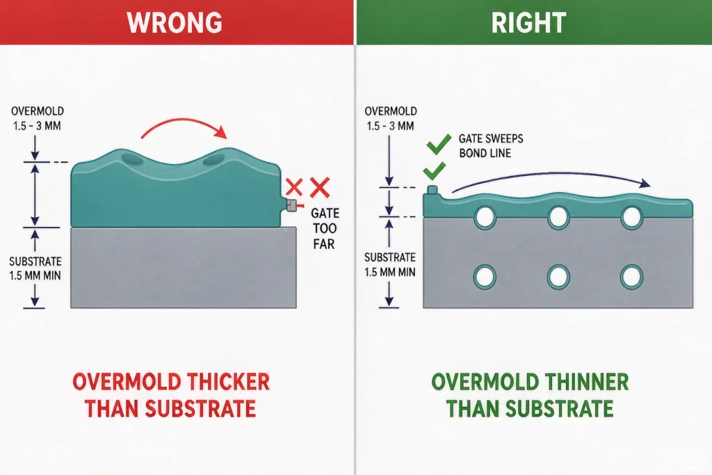
Wall Thickness Rules for Substrate and Overmold
Wall thickness matters more in overmolding than in single-shot molding because two layers shrink and cool at different rates.
- Overmold layer: typically 1.5–3 mm. Below about 1 mm you risk short shots and thin, weak sections; above about 4 mm you risk sink marks and long cooling times.
- Substrate wall: keep at least 1.5 mm so it resists the injection pressure of the second shot without deforming.
- Relative thickness: the overmold should generally be thinner than the substrate. When the soft layer is thicker than the rigid core—especially on flat or long parts—differential shrinkage causes warping.
- Transitions: use gradual steps between thicknesses to avoid flow hesitation, gas traps, and local stress.
These ranges are consistent with general single-shot rules, which our best wall thickness guide explains in more detail.
Shut-Off and Interference Control
The shut-off is the area where the second mold closes against the substrate to seal the cavity for the second shot. It is the most common source of flash or crushed substrates.
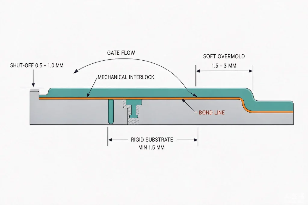
- Interference: the shut-off needs enough interference to seal without flashing, but not so much that it crushes the substrate. A typical range is about 0.5–1.0 mm, with many TPE-over-ABS parts specified around 0.8–1.0 mm.
- Surface condition: the shut-off land should be flat and clean. Damage here shows as flash on the substrate or a visible parting line on the finished part.
- Reference: shut-off is a specialized case of parting-line design; our parting line guide covers land width and draft in single-shot contexts.
If the substrate is placed by pick-and-place, the second mold needs locators that reference the substrate geometry precisely—typically pin locators or edge-reference surfaces—so the shut-off lands align within tight tolerance.
Gate Location and Flow Across the Bond
The gate should direct melt across the bonding area while the substrate surface is still hot enough to fuse. A gate placed far from the bond line lets the substrate cool before the elastomer arrives, weakening the chemical bond even with a compatible pair.
- Position the gate so flow sweeps the interface rather than landing on it and stalling.
- Avoid gating into a thick section that masks a thin bond area.
- For mechanical-interlock designs, gate location is less sensitive to chemistry but still affects fill of undercuts and grooves.
Flow analysis is often used to place the gate and size runners for two-material tools, particularly when the substrate is large or the bond area is irregular.
Mechanical Interlock Features
When the material pair cannot guarantee a chemical bond, geometry carries the load. Design interlock with these features:
- Through-holes and blind holes sized so the elastomer flows in and locks on cooling.
- Undercuts and grooves along the bond line, with draft where ejection allows.
- Textured or etched surfaces on the substrate at the interface to increase grip area.
- T-shaped or dovetail slots for higher peel resistance.
Keep interlock features away from sealing surfaces and cosmetic faces where they would show. The amount of interlock should match the expected peel and shear load; over-designing adds cost without benefit.
Shrinkage and Dimensional Control
The substrate shrinks after the first shot and the overmold shrinks after the second. If the substrate shrinks ~0.6% (e.g., ABS) and the overmold shrinks ~1.8% (e.g., TPE), the cavity dimensions must compensate for both layers independently. Parts fail dimensional inspection when the mold is cut to nominal dimensions without accounting for the overmold shrinkage.
- Specify shrinkage rates for both materials from the resin data sheet.
- Confirm the substrate is fully cooled and stable before transfer in sequential (pick-and-place) processes.
- Review tolerances against what the process can hold; our achievable tolerances guide sets expectations for two-material parts.
Overmolding DFM Checklist
Use this list before releasing the CAD for quoting:
- Bond path defined: chemical, mechanical, or both
- Substrate material fixed and compatible elastomer selected
- Overmold wall 1.5–3 mm; substrate wall ≥ 1.5 mm
- Overmold thinner than substrate where the part is flat or long
- Shut-off interference ~0.5–1.0 mm, land flat and clean
- Gate placed to sweep the bond line while substrate is hot
- Mechanical interlock added if chemical bond is risky
- Shrinkage of both layers compensated in cavity dimensions
- Draft and ejection validated for soft-elastomer features
- Tolerances reviewed against process capability
- Bond test and T1 validation planned before production
The broader manufacturing rules behind these points are in our DFM design guide.
Key Takeaways
- Design the bond interface first; wall thickness, shut-off, and gate all protect it.
- Keep the overmold layer about 1.5–3 mm and thinner than the substrate to avoid warp and sink.
- Shut-off interference around 0.5–1.0 mm seals without crushing the substrate.
- Gate across the bond line while the substrate is still hot for a chemical bond.
- Compensate shrinkage for both materials, and verify with a bond test and T1 sample.
FAQ
What wall thickness is best for overmolding?
A typical overmold layer is 1.5–3 mm, with the substrate wall at least 1.5 mm. Exact values depend on the resin and part shape and should be confirmed per grade.
How much shut-off interference do I need?
Around 0.5–1.0 mm is typical, with many TPE-over-ABS parts near 0.8–1.0 mm. Too little flashes; too much crushes the substrate.
Why does my overmold warp?
Usually differential shrinkage—the soft layer shrinks more than the rigid core. Keep the overmold thinner than the substrate and compensate both shrinkage rates in the tool.
Do I still need undercuts if the materials are chemically compatible?
Not for bond strength, but undercuts add insurance against thermal cycling and handling. For risky or non-polar pairs, interlock is required.
Upload your CAD and we will run a free DFM review focused on the bond interface, wall thickness, and shut-off before you cut tooling. Contact our engineering team to start the review.