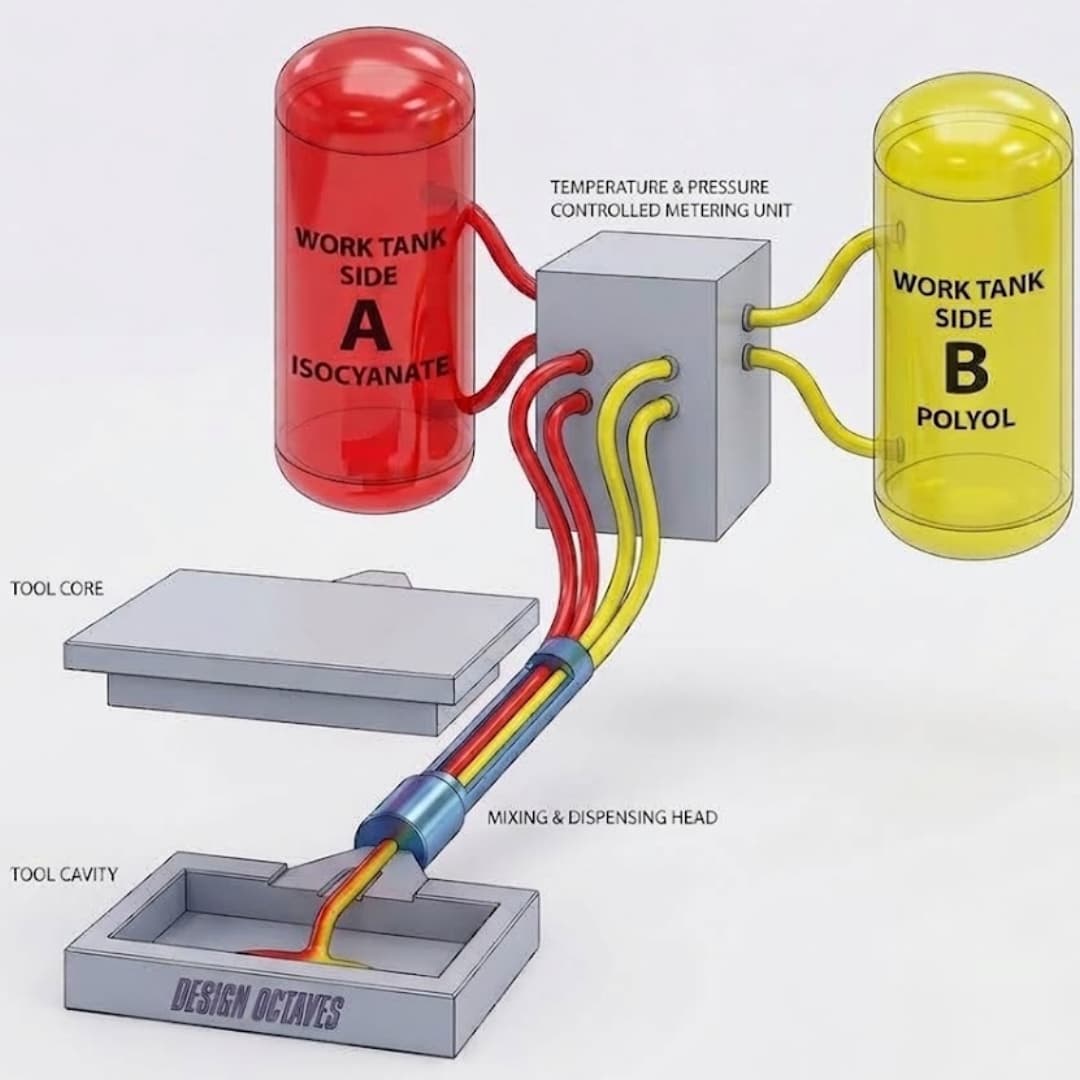

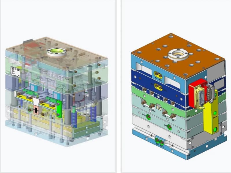
Design for Manufacturing (DFM) bridges the gap between digital CAD geometry and physical production in custom plastic injection moulding
. A flawed part design forces tooling compromises, escalates mould maintenance, and introduces structural defects such as sink marks, excessive warpage, and flash. Successful production hinges on five foundational variables: wall thickness uniformity, appropriate draft angles, strategic parting line placement, gate positioning, and internal stress mitigation.
This guide details the physical and rheological requirements for injection mould tooling. Engineers will learn how to design parts that fill predictably, eject cleanly, and maintain dimensional stability across short-run prototyping and multi-cavity volume runs.
Critical Part Geometry: Wall Thickness, Radii, and Transition Rules
Wall thickness dictates melt flow behavior, cooling cycle duration, and residual stress distribution. Maintaining a uniform nominal wall thickness across the entire part profile prevents differential shrinkage—the root cause of sink marks, void formation, and component warpage.
Poor design with differential shrinkage occurs when a thick section cools more slowly than a thin wall, leading to sink marks and internal voids in the thick area, while the thin wall freezes prematurely and blocks packing pressure from reaching the thicker region—resulting in surface defects and compromised internal quality. The optimized DFM approach addresses this by adopting a uniform nominal wall thickness throughout the part, coring out the thick zones to match that uniform dimension, and adding ribs where material is removed to restore rigidity and strength. This ensures even cooling, effective pressure transfer, and consistent part quality, with the ribs compensating for any loss in stiffness
Nominal Wall Thickness and Flow Length Considerations
When designing for plastic injection moulding services, wall dimensions must match the specific flow characteristics and shrink rates of the selected resin. Thin sections may freeze prematurely (hesitation), causing short shots. Excessively thick walls increase cycle times exponentially, as plastic acts as a thermal insulator where cooling time scales roughly with the square of the wall thickness.
| Resin Type | Typical Nominal Wall Range | Shrinkage Rate Range (Approx.) | Key Design Consideration |
| Polypropylene (PP) | 0.8 mm – 3.8 mm | 1.0% – 2.5% | High shrinkage; requires precise rib-to-wall ratios |
| ABS | 1.1 mm – 3.5 mm | 0.4% – 0.8% | Amorphous; predictable flow, sensitive to sink marks |
| Polyamide (Nylon / PA66) | 0.8 mm – 3.0 mm | 1.0% – 3.0% | Hygroscopic; crystalline structure demands uniform cooling |
| Polycarbonate (PC) | 1.0 mm – 4.0 mm | 0.5% – 0.7% | High melt viscosity; requires generous radii to limit stress |
Note: Specific wall ranges vary based on glass-fibre reinforcement, flow length-to-thickness (L/T) ratios, and processing conditions. Verify exact parameters with resin technical datasheets prior to cutting steel.
When transitioning between distinct wall thicknesses cannot be avoided, use gradual chamfers or ramps. The transition length should be at least three times the difference in thickness (3:1 taper) to maintain laminar melt flow and distribute internal shear stresses evenly.
Fillets vs. Sharp Corners: Mitigating Stress Concentrations and Mould Wear
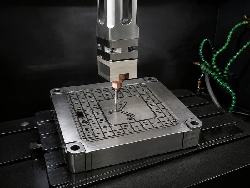
Sharp internal corners are primary failure points in injection-moulded components and significantly increase tooling fabrication costs. A sharp corner creates an abrupt change in flow direction, generates localized stress spikes during cooling, and requires wire EDM (Electrical Discharge Machining) to produce sharp internal features on mould cavities.
- Inside Radii (Ri): Specify an internal radius of at least 50% to 60% of the adjacent nominal wall thickness (0.5t to 0.6t).
- Outside Radii (Ro): Set outside radii equal to the inside radius plus the wall thickness (Ro = Ri + t) to preserve uniform cross-sectional thickness through the bend.
Generous fillets reduce injection pressure requirements, streamline melt front advancement, and prevent premature cracking under mechanical fatigue.
Draft Angles and Surface Finishes: Ensuring Seamless Part Ejection
Draft—the dimensional taper applied to vertical surfaces parallel to the direction of mould opening—is required to release parts without scuffing, drag marks, or excessive ejector force.
In demoulding mechanics, a zero‑draft (0°) condition keeps the mould steel and part surface in full contact throughout ejection, resulting in continuous frictional shear over the whole stroke. With a draft angle of 1° to 2°, the taper provides clean clearance within the first 0.1 mm of travel, effectively reducing friction and wear.
As melted thermoplastic cools inside the cavity, it shrinks onto male tool features (cores) while pulling away from female tool features (cavities). Insufficient draft traps vacuum against the cavity, increases friction on the core, and causes ejector pins to punch through or distort thin features.
Minimum Draft Angle Rules by Feature Depth and Texture Level
A standard baseline for untextured, polished faces is 1° to 2° of draft per side, providing adequate clearance with minimal dimensional variation over depth. However, deeper draws and textured tools require larger drafts:
- Standard Micro-Finishes (SPI A or B): Minimum 1° per side; add 1° for every 25 mm of core depth.
- Light Surface Textures (SPI C or VDI 18–24): Minimum 1.5° to 2° per side.
- Heavy Spark Erosion / Grained Textures (Mold-Tech / VDI 30+): Add roughly 1° to 1.5° of draft for every 0.025 mm (0.001 in) of texture depth. Textures act as micro-undercuts; inadequate draft shears the grain off the tool face and leaves burnished scuffs on the part.
- Internal Ribs and Tall Features: 0.5° minimum per side to prevent rib binding, balanced against wall thickness limits at the rib tip.
Ribs, Bosses, and Structural Gussets: Balancing Strength and Sink Prevention
Reinforcing ribs increase structural stiffness without adding excessive bulk, but thick rib bases create localized hot spots that pull inward upon cooling, leaving noticeable sink marks on cosmetic class-A surfaces.
- Rib Base Thickness: Keep the thickness at the base of the rib between 40% and 60% of the nominal mating wall thickness. For low-shrinkage materials (e.g., PC), 60% is acceptable; high-shrink materials (e.g., PP, PE) require a tighter 40% threshold.
- Rib Height: Restrict total height to no more than three times the nominal wall thickness (3t) to prevent venting issues and rib filling defects.
- Rib Spacing: Maintain a minimum distance of twice the nominal wall (2t) between parallel ribs to facilitate conventional CNC milling and cooling channel routing within the mould core.
- Screw Bosses: Core out bosses down to the base level to avoid thick thermal masses. Connect bosses to adjacent perimeter walls using structural gussets rather than standalone cylindrical columns.
Mould Architecture: Parting Lines, Side Actions, and Shut-Offs
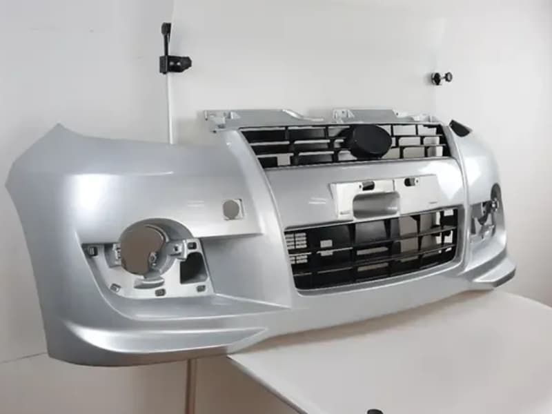
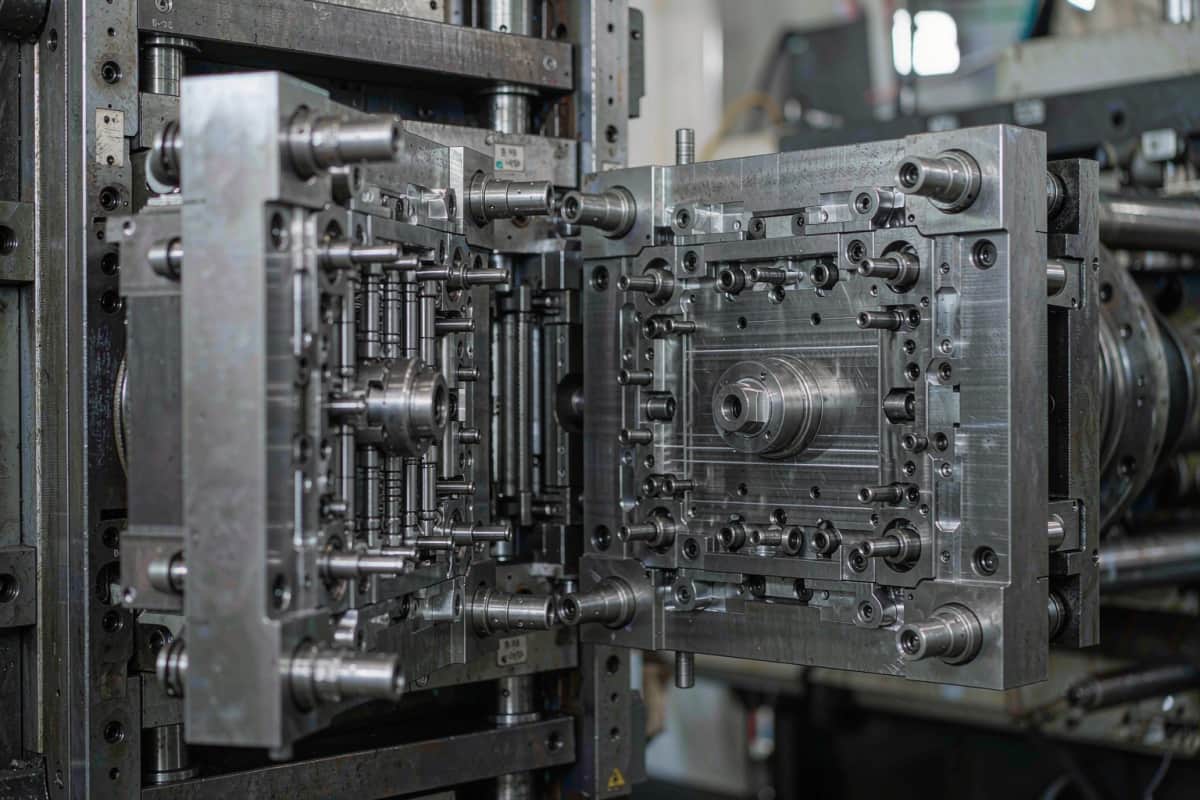
The mechanical layout of an injection mould dictates piece-part cost, flash potential, and aesthetic witness lines. Structural engineers must visualize where the two primary halves of the mould—the cavity (A-side) and the core (B-side)—meet.
Mould opening direction (pull vector) is along the vertical axis. The A‑side cavity is located above the parting line plane, and the B‑side core is below it. The parting line itself forms a witness line on the moulded part. During mould opening, the A‑side and B‑side separate vertically – typically the core retracts downward while the cavity moves upward, or vice versa, depending on the machine configuration. The pull vector defines the primary direction for demoulding and determines which features require draft angles.
Selecting Optimal Parting Lines to Balance Flash and Aesthetics
The parting line defines the perimeter where the mould closes under clamping pressure. A planar parting line perpendicular to the draw direction is the most stable and cost-effective to mill and shut off. Curved, stepped, or complex 3D parting lines increase CNC surfacing time, require manual benching, and are more vulnerable to parting-line wear and localized flash over extended cycles.
Locate the parting line along a sharp external edge rather than across a flat visual surface whenever possible. This masks the unavoidable parting seam (witness line) and simplifies deflashing or secondary finishing operations.
Eliminating Undercuts or Managing Them via Sliders and Lifters
Undercuts are part features—such as side holes, internal snaps, clips, or exterior threads—that prevent the part from ejecting directly along the primary pull vector. Managing undercuts directly impacts tool complexity:
- Passing Shut-Offs (By-Pass Coring): Many holes and clips can be formed without moving actions. By incorporating through-holes in the bottom face, vertical mould shut-offs can telescope through the part to form internal catches without mechanical sliders.
- Side-Action Sliders: When exterior holes or latches cannot be modified, pneumatic or cam-driven side-action slides pull the core pin outward before the mould opens. Sliders add moving wear surfaces, require robust lubrication, and raise the initial tooling investment.
- Internal Lifters: Internal undercuts require mechanical lifters that travel at an angle during the ejection stroke. Lifters require clearance to slide inward without colliding with ribs or opposing features.
Where undercuts are required, planning side-pull trajectories early preserves structural rigidity and prevents costly tool modifications during injection mould making
Gating, Venting, and Ejection Systems: Engineering the Flow Path
Tooling design governs how molten resin enters the cavity, how displaced gas escapes, and how the solidified component is ejected.
Melt delivery and venting schematic: The molten plastic flows from the runner through the gate into the mould cavity. The cavity is vented with air vents having a gap thickness of 0.015 to 0.038 mm, allowing trapped gases to escape during filling. An ejector pin is also present in the tool, which leaves a witness mark on the B‑side of the part after ejection.
Gate Type Selection: Edge, Submarine, Direct Sprue, and Hot Runners
Gates regulate the volume, pressure, and velocity of resin entering the mould. The gate should be located at the thickest section of the part to permit packing pressure through the thinner sections, preventing premature gate freeze-off and subsequent voids.
| Gate Type | Vestige / Mark Left | Operation Style | Typical Suitability |
| Edge Gate | Visible rectangular scar | Manual trimming / Degating | Flat parts, medium-to-heavy structural parts |
| Submarine (Tunnel) Gate | Small circular pip | Automatic shearing upon ejection | High-volume production, parts without exterior scars |
| Direct Sprue Gate | Large circular vestige | Machined or clipped manually | Single-cavity deep buckets, heavy industrial housings |
| Hot Runner Valve Gate | Minimal ring/flush mark | Fully automatic, runnerless | Multi-cavity packaging, thin-wall medical components |
Gate selection directly influences weld line (knit line) locations. Weld lines form where two melt fronts rejoin after flowing around a core pin or internal boss. Position gates so that weld lines occur in areas with lower structural stress and minimal visual exposure.
Venting and Ejector Pin Placement Considerations
As molten plastic enters the cavity under high pressure, air and volatile gases inside the mould must escape. Inadequate venting traps gas, causing dieseling (localized scorch marks) or short shots where the cavity fails to fill completely.
- Venting Dimensions: Vents must be ground along parting lines, typically sized between 0.015 mm and 0.038 mm deep (depending on polymer viscosity) and 3 mm to 6 mm wide. High-viscosity materials (e.g., PC) tolerate deeper vents, whereas low-viscosity polymers (e.g., PA) flash if vents exceed 0.015 mm.
- Ejector Pin Positioning: Place ejector pins against non-cosmetic surfaces (almost exclusively on the B-side core). Provide wide, flat bearing surfaces directly beneath internal walls, rib intersections, and perimeter bosses where demoulding drag is highest. Distributing ejection force evenly across the part prevents pin-push stress marks, localized whitening, or punch-through damage during automated cycling under custom injection moulding services.
From Rapid Prototyping to Production Tooling: Validating the DFM Cycle
Moving directly from a CAD model to multi-cavity hardened steel tooling carries unnecessary financial and operational risk. A structured validation process confirms fit, form, and mechanical performance prior to tool steel cutting.
ENGINEERING VALIDATION STAGES:
1. CAD DFM Review ──► 2. Additive/CNC Check ──► 3. Bridge Tooling ──► 4. Production Tooling
(Thickness/Draft) (Fit & Function) (T1 Samples/PPAP) (Multi-cavity Steel)
- Preliminary Digital DFM Audit: Run automated mould filling simulations to identify fill patterns, high shear zones, air traps, and predicted warpage vectors.
- Functional Prototype Verification: Fabricate high-fidelity concept models via rapid prototyping solutions (such as SLA, SLS, or CNC machining). These prototypes confirm mechanical clearances, verify assembly snap-fits, and validate ergonomics before committing to steel cut geometries.
- Bridge/Soft Tooling (Aluminum or Pre-Hardened P20): For low-volume production or clinical testing, bridge moulds supply production-intent thermoplastic parts for regulatory testing, destructive mechanical validation, and packaging trials.
- Production Tooling Sign-Off: Once part parameters and shrink rates are confirmed on physical samples, production tooling proceeds to cut hardened steels (such as H13, S136, or NAK80) supported by a stringent quality system for dimensional stability over high-cycle volumes.
The Pre-Tooling DFM Checklist: What to Verify Before Sign-Off
Review the CAD model against this engineering checklist before releasing final step files to your injection mould manufacturer:
- [ ] Wall Uniformity: Have all unnecessary solid sections been cored out to preserve an even nominal wall thickness?
- [ ] Corner Radii: Are all internal sharp corners broken with fillets matching at least $0.5t$ to reduce localized stress concentrations?
- [ ] Draft Angles Applied: Have all functional vertical walls received a minimum of 1° to 1.5° draft, with textured faces drafted an additional 1° to 1.5° per 0.025 mm of grain depth?
- [ ] Rib Base Dimensions: Are ribs designed with base thicknesses limited to 40%–60% of the nominal wall, accompanied by at least 0.5° of draft per side?
- [ ] Boss Coring & Clearance: Are all screw bosses cored down to the nominal wall, gusseted to nearby features, and drafted on both internal and external diameters?
- [ ] Parting Line Simplification: Is the parting line positioned along natural part edges to minimize step-downs, eliminate flash risks, and conceal witness seams?
- [ ] Undercut Minimization: Have internal and external undercuts been eliminated through by-pass coring where practical, or accommodated with clearance for sliders/lifters?
- [ ] Gate & Ejector Location Clearance: Have designated non-cosmetic surfaces been flagged on 2D engineering drawings for ejector pin marks and gate vestige trimming?
- [ ] Critical Dimensions & Tolerances: Are critical-to-quality (CTQ) tolerances clearly distinguished from general non-critical profiles, allowing toolmakers to build steel-safe features for fine-tuning?
Key Takeaways
- Maintain Uniform Wall Thickness: Inconsistent wall thickness is the primary driver of internal voids, localized sink marks, and thermal warpage. Core out thick intersections and add ribs for rigidity.
- Apply Draft Early: Implement a minimum of 1° to 2° draft on all vertical walls parallel to the pull direction. Add an extra 1° to 1.5° per 0.025 mm of texture depth on grained surfaces.
- Control Rib-to-Wall Ratios: Limit the base of structural ribs to 40%–60% of the mating wall thickness to eliminate sink marks on class-A visual faces.
- Design for Parting Line Simplicity: Planar parting lines reduce tooling costs, eliminate flash vulnerabilities, and simplify maintenance relative to stepped or 3D shut-offs.
- Validate Before Cutting Steel: Employ functional prototypes to verify fit and tolerances before locking CAD geometry for high-volume tooling.
Injection Moulding DFM: Frequently Asked Technical Questions
What is the standard minimum draft angle required for plastic injection moulding?
A standard baseline of 1° to 2° per side is recommended for smooth, untextured surfaces with normal draw depths. For parts featuring molded-in textures (such as SPI or VDI patterns), add 1° to 1.5° of draft for every 0.025 mm (0.001 in) of texture depth to prevent scuff marks and drag damage during part ejection.
How can engineers reduce injection mould making tooling costs during the initial design phase?
Tooling costs are primarily driven by mechanical complexity and machining hours. Engineers can reduce tooling capital by eliminating undercuts using through-core shut-offs instead of side-action sliders, keeping parting lines planar, designing standard uniform walls that minimize EDM operations, and avoiding deep, narrow slots that require specialized electrode milling.
What is the primary difference between cold runner and hot runner mould systems in custom projects?
Cold runner systems route plastic through unheated channels that solidify and eject with each cycle, requiring regrinding or manual separation from the part. Hot runner systems use electrically heated manifolds to keep resin molten up to the cavity entrance. This eliminates runner scrap and shortens cycle times, but increases upfront tooling costs and requires more complex process controls.
Why does non-uniform wall thickness cause major warpage in injection-moulded parts?
Different wall thicknesses cool at different rates. Thinner sections solidify and lock their crystal structure quickly, while thicker sections cool slowly and continue to contract. This thermal imbalance creates uneven internal stresses that pull against the frozen perimeter, bending and warping the part as it cools outside the mould. For more detailed production parameters and technical clarifications, review the GoodTech manufacturing FAQ
Partner with GoodTech for Precision Mould Making and DFM Review
Optimizing part geometry for injection moulding requires balancing structural performance, cosmetic criteria, and physical mould design constraints. Early collaboration with an experienced manufacturing partner flags tooling obstacles before steel cutting begins, protecting your development budget and schedule.
GoodTech provides end-to-end tooling and injection moulding capabilities—from initial CAD reviews and prototype validation to multi-cavity production tooling and tight-tolerance quality inspection. To review your next project, evaluate wall configurations, or request an engineering review, contact our engineering team
to receive a comprehensive DFM assessment and custom injection moulding quote.