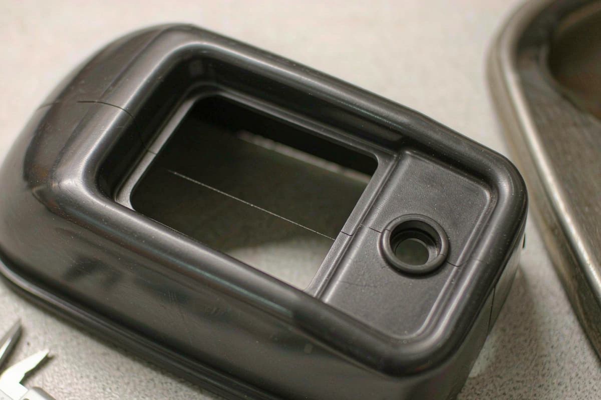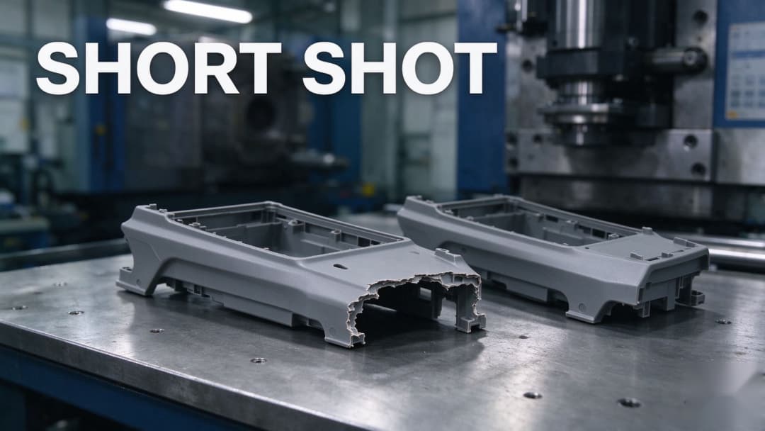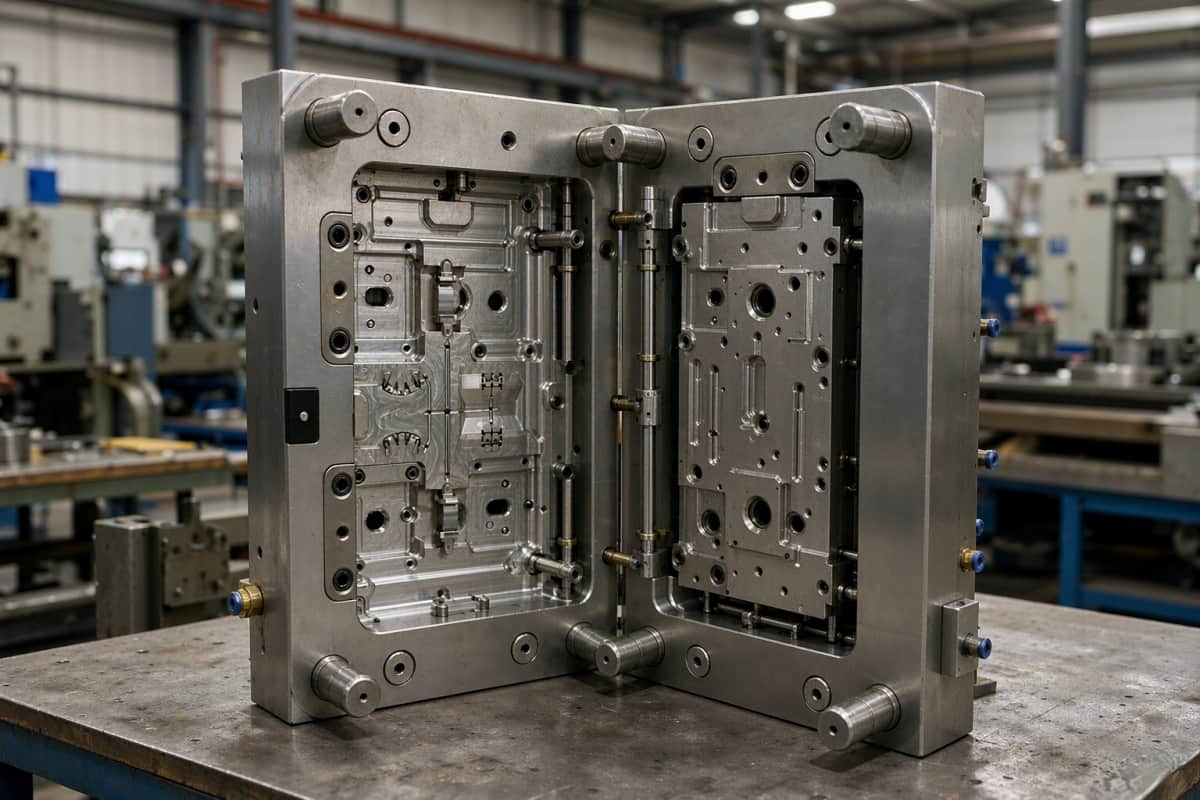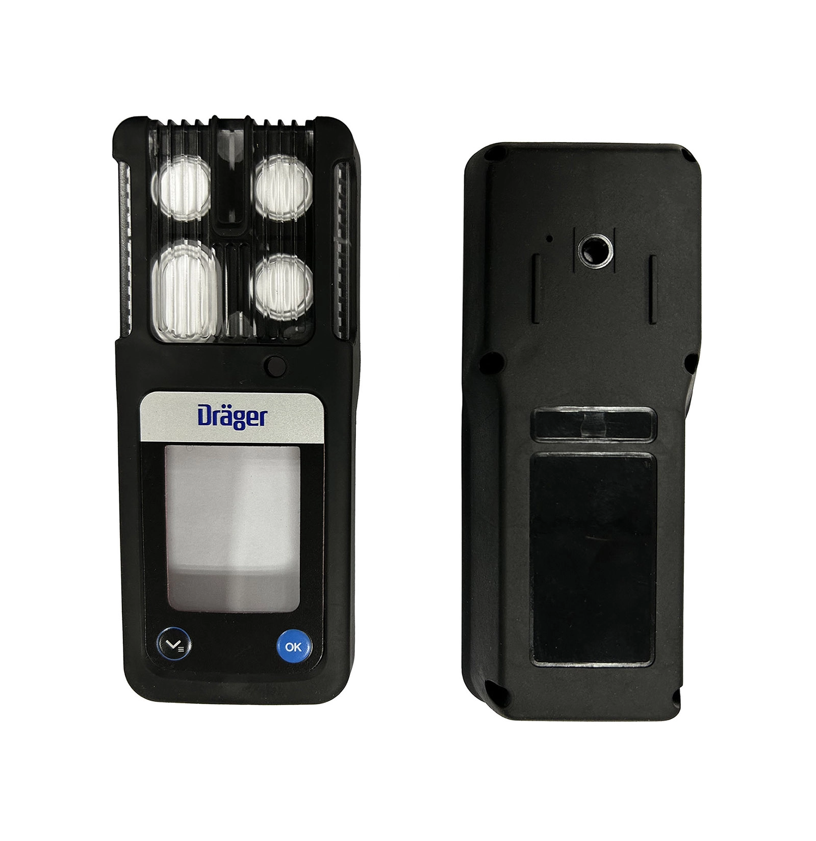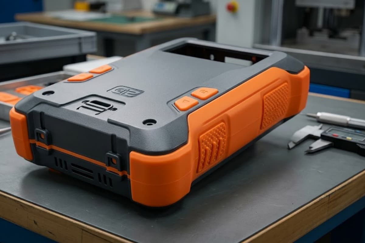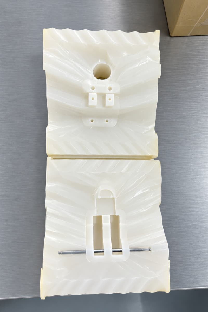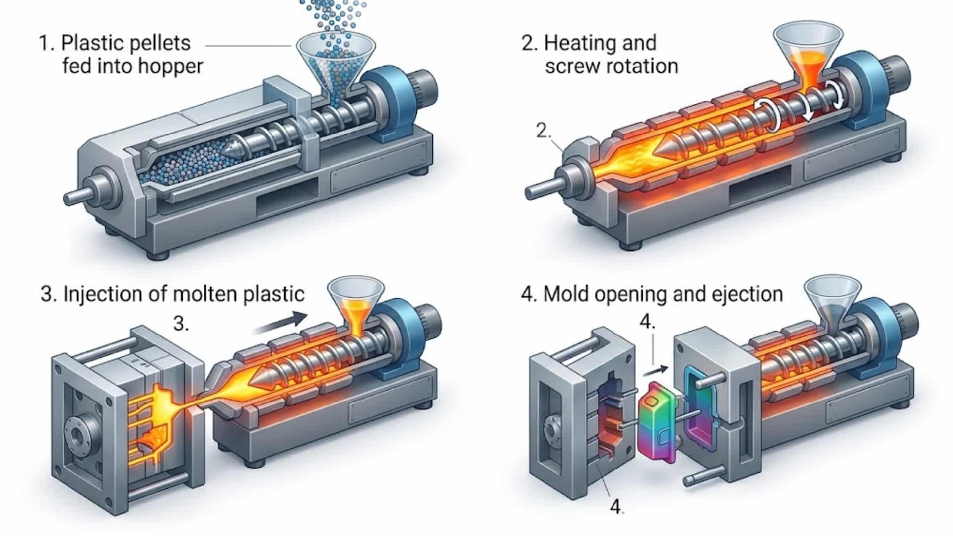

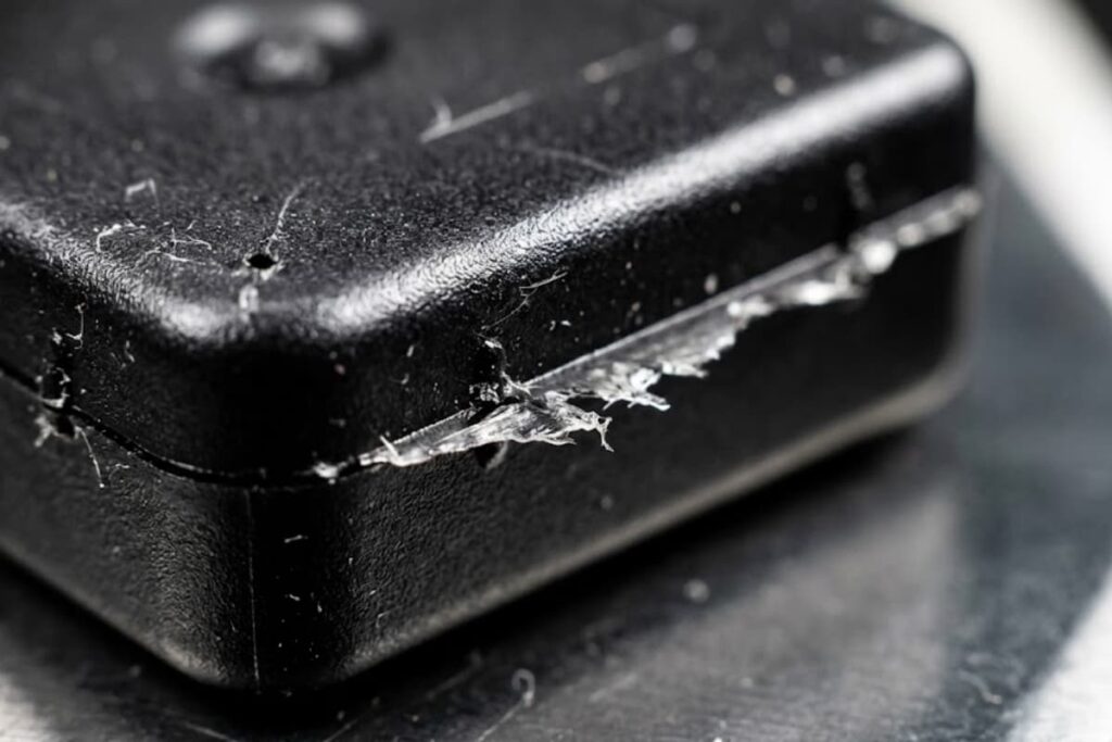
Flash — the thin fin of plastic that squeezes out at the parting line, around ejector pins, or along a vent — is one of the most common injection molding defects. It is also one of the most misunderstood, because it is rarely caused by a single setting. Flash is fundamentally a force-balance problem: it appears when melt pressure inside the cavity exceeds the force holding the mold shut. Light flash means trimming cost; heavy flash can hold the mold slightly open, damage the parting surface, push dimensions out of tolerance, and scrap whole batches.
This guide keeps it simple: the seven root causes, vent-depth and clamp-tonnage charts by material, a 7-step troubleshooting sequence for the shop floor, and the design decisions that prevent flash before the tool is cut. For the full defect catalog, see our injection molding defects prevention guide.
1. The 7 Root Causes of Flash
| # | Cause | What happens | First check |
|---|---|---|---|
| 1 | Insufficient clamp tonnage | Projected area is too large; injection pressure cracks the mold open | Recalculate tonnage; move to a bigger press |
| 2 | Hold pressure too high / too long | Melt is forced into gaps after the gate has frozen | Run a gate-freeze study; trim the hold profile |
| 3 | Melt temperature too high | Lower viscosity lets plastic creep into tiny clearances | Reduce in 5–10 °C steps, keeping the part full |
| 4 | Worn or dirty parting surface | The mold never fully closes; gaps grow with wear and residue | Clean first, then check contact under magnification |
| 5 | Vents cut too deep | Beyond the resin’s overflow limit, the vent becomes an escape path | Re-cut to the resin-specific depth (Section 2) |
| 6 | Weak mold base / poor support | Plates flex and open slightly under cavity pressure | Add support pillars; thicken the support plate |
| 7 | Wet or degraded resin | Moisture drops melt viscosity sharply (nylon, PC, PBT) | Dry to spec — e.g. below 0.2% moisture for PA |
A quick way to read this table: causes 1–3 are process-side (free to change), causes 4–6 are tool-side (costly), and cause 7 is material-side. Always rule out the free ones first.
2. Vent Depth and Clamp Tonnage by Material
Different resins flow very differently, so a tool that runs ABS cleanly can flash when switched to a high-flow polypropylene or undried nylon. Whenever you change materials, re-check vent depth and clamp force:
| Material | Flash risk | Typical vent land depth | Clamp rule of thumb |
|---|---|---|---|
| PP / PE | High | 0.02 mm (0.001″) | 2–3.5 t/in² |
| PS / ABS | Medium | 0.015 mm (0.0006″) | 3–4 t/in² |
| PC / PMMA | Low–medium | 0.01 mm (0.0004″) | 4–5 t/in² |
| PA (nylon) / POM | Very high | 0.008–0.01 mm (0.0003″) | 4–6 t/in² |
Tip: if a tool suddenly starts flashing after a few hundred thousand shots of glass-filled material (PA-GF, PP-GF), check the vents first — glass fiber erosion has very likely deepened them.
3. The 7-Step Troubleshooting Sequence (Process Before Steel)
Process changes are cheap and reversible; mold steel is not. Work through this order, changing one variable at a time and weighing parts after each step:
- Check drying. Confirm hygroscopic resins (PA, PC, PBT) were actually dried to spec.
- Run a gate-freeze study. Cut hold time back to the moment the gate seals — anything longer only forces material into gaps.
- Reduce hold pressure in small steps until parts just begin to show sink, then back off.
- Lower melt temperature in 5–10 °C steps while confirming the part still fills.
- Check the velocity-to-pressure changeover. Switching too late spikes end-of-fill pressure; move it earlier.
- Recalculate clamp force — including the runner in the projected area — and check platen parallelism.
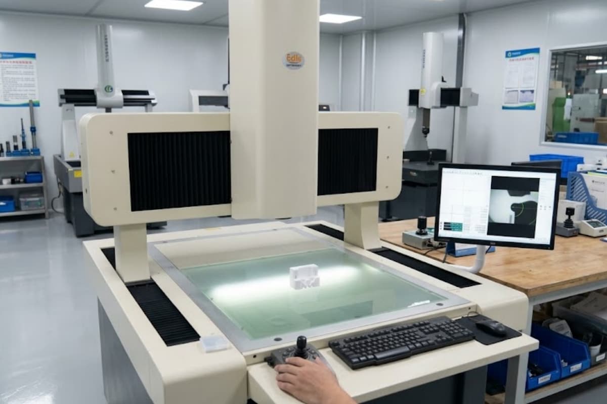
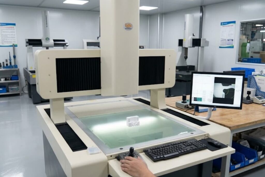
- Only then inspect the mold. Clean the parting surface and check for crush marks, scoring, or residue under magnification.
If flash survives a verified process window, the root cause is almost certainly in the tool — don’t start grinding before you know which surface is the problem.
4. Preventing Flash at the DFM Stage
Designing flash out costs far less than fixing it in production. The highest-leverage decisions:
- Uniform wall thickness. Thick-to-thin transitions demand high packing pressure to fight sink — and that same pressure flashes the tool. See our injection molding DFM design guide.
- Gate size and location. A balanced gate lets the part pack at lower pressure. Compare options in our gate design guide.
- Keep the parting line off cosmetic faces, and use flat lines or shut-off angles of at least 3° where steel meets steel — placement strategy is covered in our parting line design guide.
- Plan for deflashing early. Soft TPEs and tight-tolerance parts may always show micro-flash; decide before production whether trimming, tumbling, or cryogenic deflashing belongs in the quotation.
5. When Flash Means the Tool Needs Repair
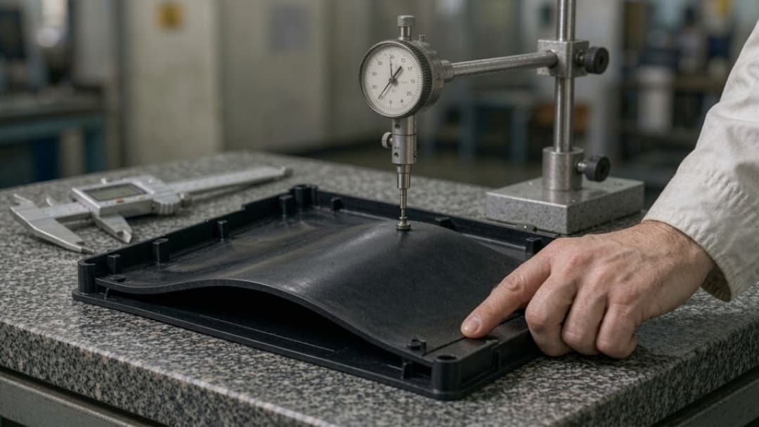
Diagnosis is in the timing. Flash that appears suddenly after a process or material change is usually process- or material-side. Flash that gradually worsens over hundreds of thousands of shots points to a worn parting surface or eroded vents. The repair path, cheapest first: clean and verify full closure at operating temperature → re-cut vents to resin-specific depth → restore the parting surface flatness (typically 0.01–0.02 mm fit range) → add support pillars if plates are flexing. Tracking flash occurrence as an SPC metric catches gradual wear before it produces sustained scrap; our mold maintenance guide covers the preventive schedule. Molds inspected by shot count — not calendar time — simply flash less over their life.
FAQ
How much flash is acceptable on a molded part?
For general commercial parts, flash height up to about 0.1–0.15 mm is commonly accepted and trimmed. Medical, optical, and sealing surfaces are typically specified much tighter (≤0.05 mm or flash-free). Define the limit on the drawing — “no visible flash” is not a specification.
Does flash mean the mold is damaged?
Not necessarily. Flash right after a process or material change is usually process-side. Flash that gradually worsens over many thousands of shots points to parting-line or vent wear.
Which materials flash most easily?
Low-viscosity resins: high-MFI polypropylene, undried nylon, and POM. Drying to spec and verifying vent depth before running these materials removes most of the risk.
Can flash be prevented by design?
Largely, yes. Uniform walls, balanced gating, a verified tonnage calculation (including the runner), and resin-appropriate vent depths remove most of the pressure drivers behind flash.
Related Reading
- Common Injection Molding Defects: Prevention Guide
- Injection Molding Warpage: Causes, Fixes and Prevention
- Injection Molding Gate Types: 8 Designs Compared
- Precision Injection Molding DFM Design Guide
- Injection Mold Maintenance Guide: Extending Tool Life
Flash is a solvable defect — but only when the process, material, and tool are reviewed as one system. Our engineering team reviews tonnage, venting, and packing strategy with every custom injection molding project before steel is cut. If you have a recurring flash problem, send the part drawing, resin grade, and process window — a focused engineering review is faster than a new tool.