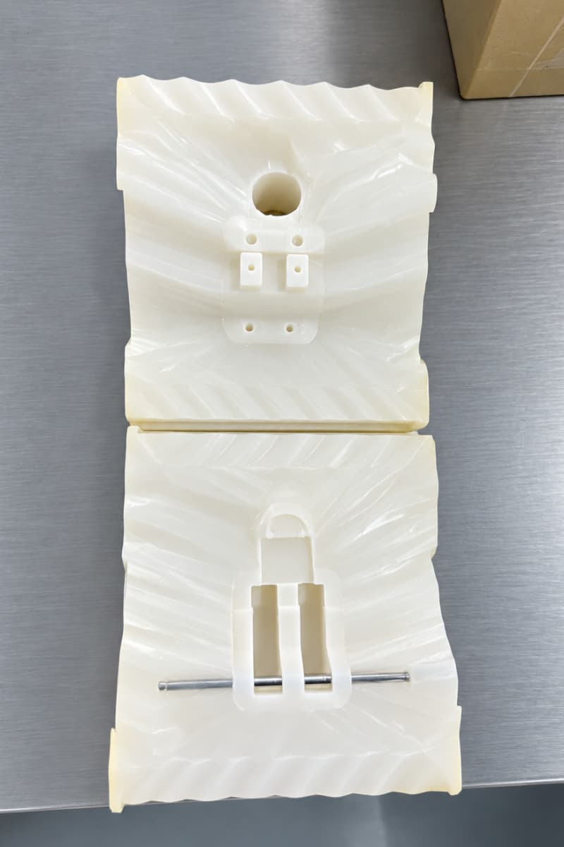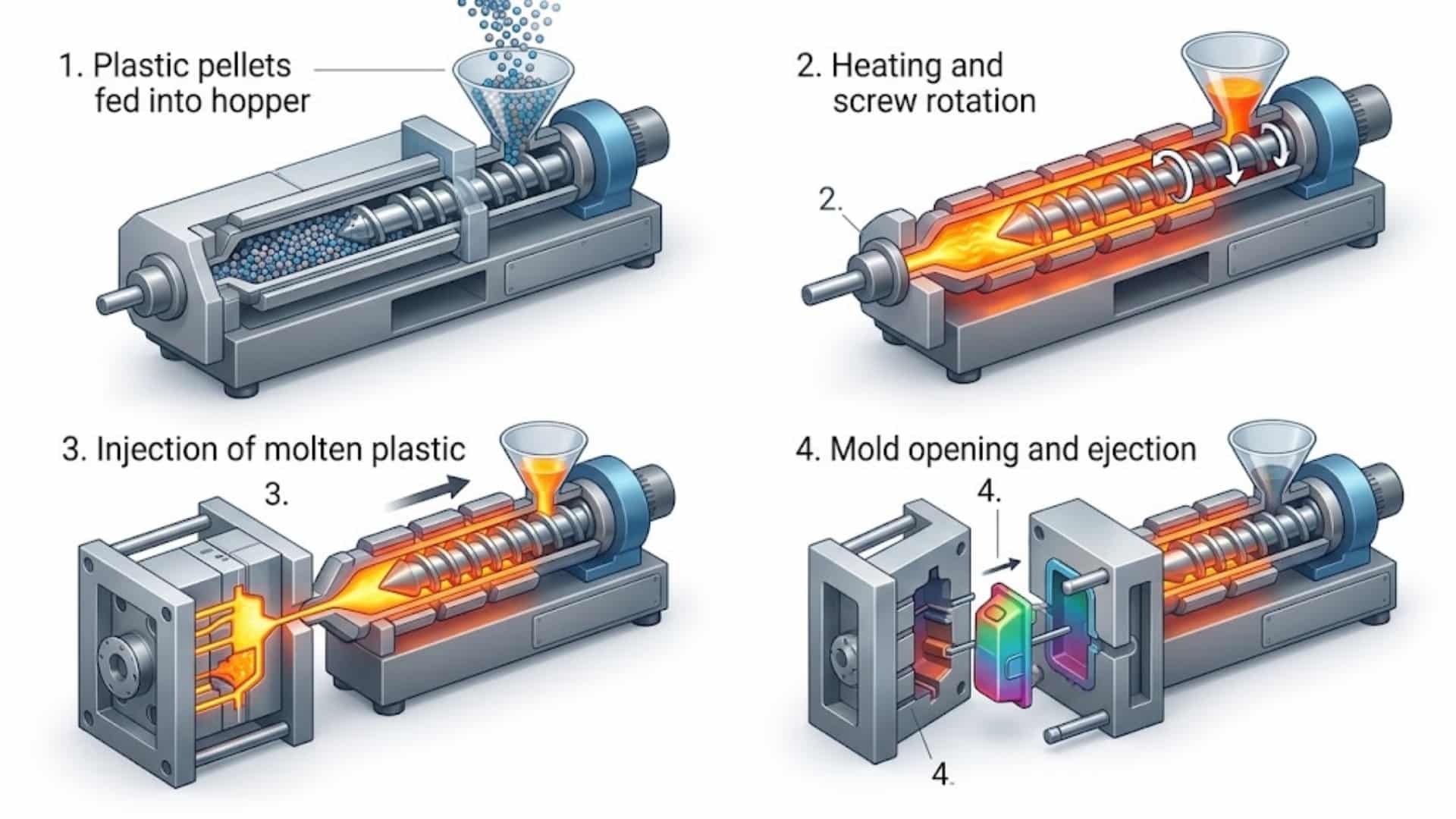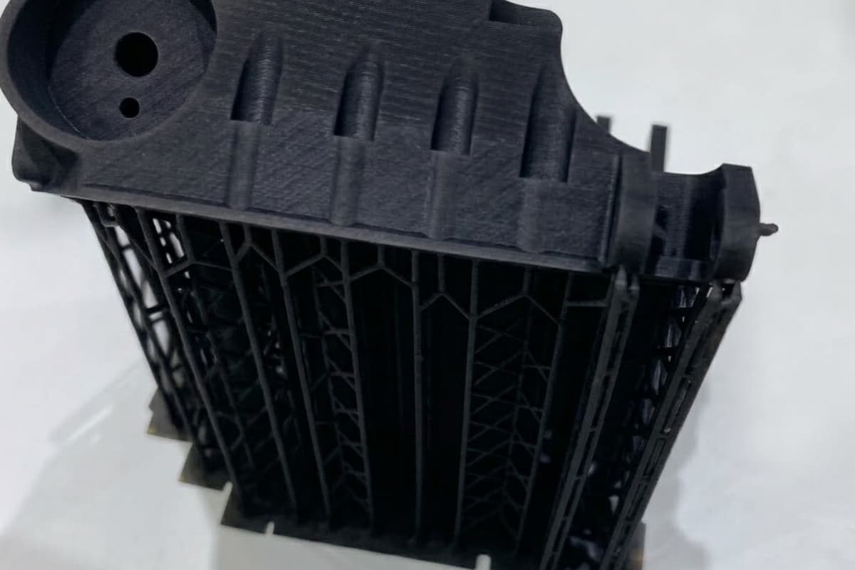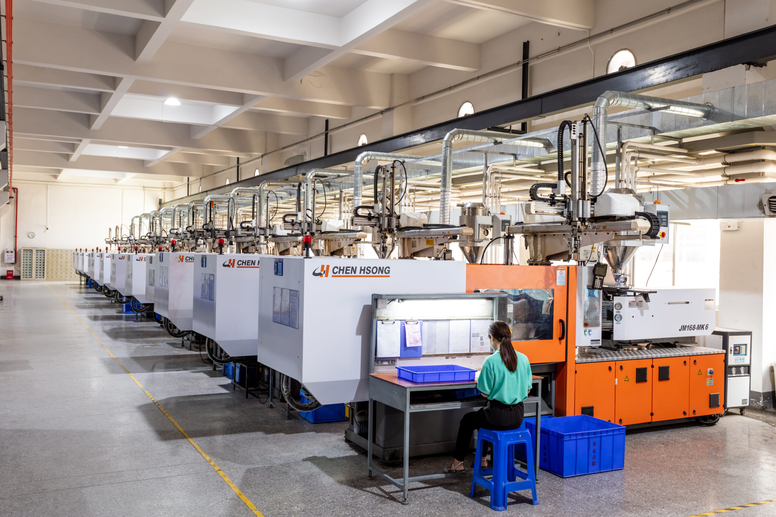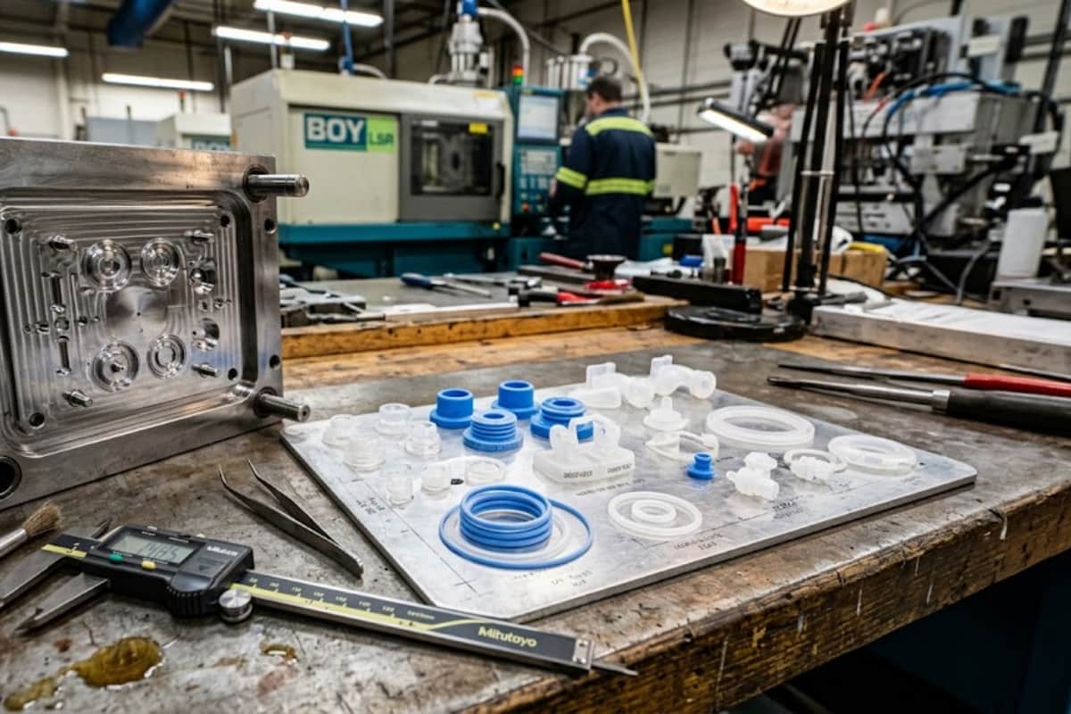

Plastic injection molding defects such as sink marks, warpage, flash, and short shots directly increase scrap rates, delay production schedules, and drive up secondary tooling costs. Resolving these issues requires an integrated engineering approach: while machine-side parameter adjustments offer immediate triage, permanent defect prevention relies on robust injection molding design, proper tooling geometry, and precise material selection. Of these, warpage is the one that shows up late — sometimes a full day after molding — so we treat it in a separate guide to why parts warp and how to prevent it.
This guide breaks down the physical root causes behind major injection molding defects, outlines actionable Design for Manufacturability (DFM) rules, and details how a systematic manufacturing workflow ensures dimensional stability for production-grade plastic components.
Why Defect Prevention Starts at the Design Stage
Attempting to resolve structural defects solely at the injection molding machine frequently leads to narrow processing windows, extended cycle times, and recurring batch inconsistency. Adjusting parameters such as injection pressure, melt temperature, or packing time can temporarily compensate for minor process fluctuations, but machine controls cannot overcome fundamental geometric flaws like non-uniform wall thickness, improper gate placement, or insufficient draft angles.
Addressing part geometry and tooling construction during the initial DFM phase establishes the widest possible molding window. Integrating design rules early when sourcing custom injection molding services
mitigates thermal stresses, balances cavity filling, and prevents expensive tooling modifications after steel has been cut.
Quick Diagnostic Matrix: 6 Common Injection Molding Defects at a Glance
| Defect Type | Visual / Dimensional Symptom | Primary Root Cause Category | Key Corrective Action |
| Sink Marks & Voids | Surface depressions or internal vacuum pockets in thick sections | Part Design & Packing Pressure | Maintain uniform nominal wall thickness; core out thick sections; optimize rib-to-wall ratios. |
| Warpage & Distortion | Unintended twisting, bending, or out-of-spec dimensional flatness | Tooling Design & Thermal Cooling | Balance cooling line placement; equalize shrinkage; maintain uniform nominal wall thickness. |
| Flash (Burrs) | Thin material excess protruding along the parting line or ejector pins | Tooling Precision & Clamping Force | Recalculate clamping tonnage; re-machine parting line shut-offs; inspect mold wear. |
| Short Shots | Incomplete filling of the mold cavity, typically in thin ribs or far edges | Melt Rheology, Venting & Tooling | Increase venting capacity; enlarge gates/runners; optimize injection speed and pressure. |
| Weld Lines (Knit Lines) | Visible lines or mechanical weak points where two melt fronts meet | Gate Placement & Melt Temperature | Reposition gates to relocate knit lines away from high-stress areas; increase melt/mold temperature. |
| Burn Marks | Black or dark brown discoloration on the trailing edges of the part | Tooling Venting & Injection Speed | Clear clogged vents; add perimeter/ejector pin venting; reduce injection speed at end-of-fill. |
In-Depth Defect Breakdown: Causes and Preventive Measures
1. Sink Marks and Voids: Wall Thickness and Gate Optimization
Sink marks appear as localized surface depressions over thick features, whereas vacuum voids develop internally when outer skins freeze before inner cores solidify. Both stem from volumetric shrinkage during phase transition from liquid to solid polymer.
- Part Design Rules:
- Maintain nominal wall thickness across the entire part geometry.
- Design reinforcing rib base thickness between 40% to 60% of the adjacent nominal wall thickness.
- Core out solid bosses, heavy transitions, and structural intersections.
- Tooling Solutions:
- Relocate gates directly into the heaviest wall sections to ensure effective packing pressure before gate freeze-off occurs.
- Verify through plastic mold fabrication standards that runner cross-sections allow sufficient packing duration.
2. Warpage and Distortion: Differential Cooling and Material Shrinkage
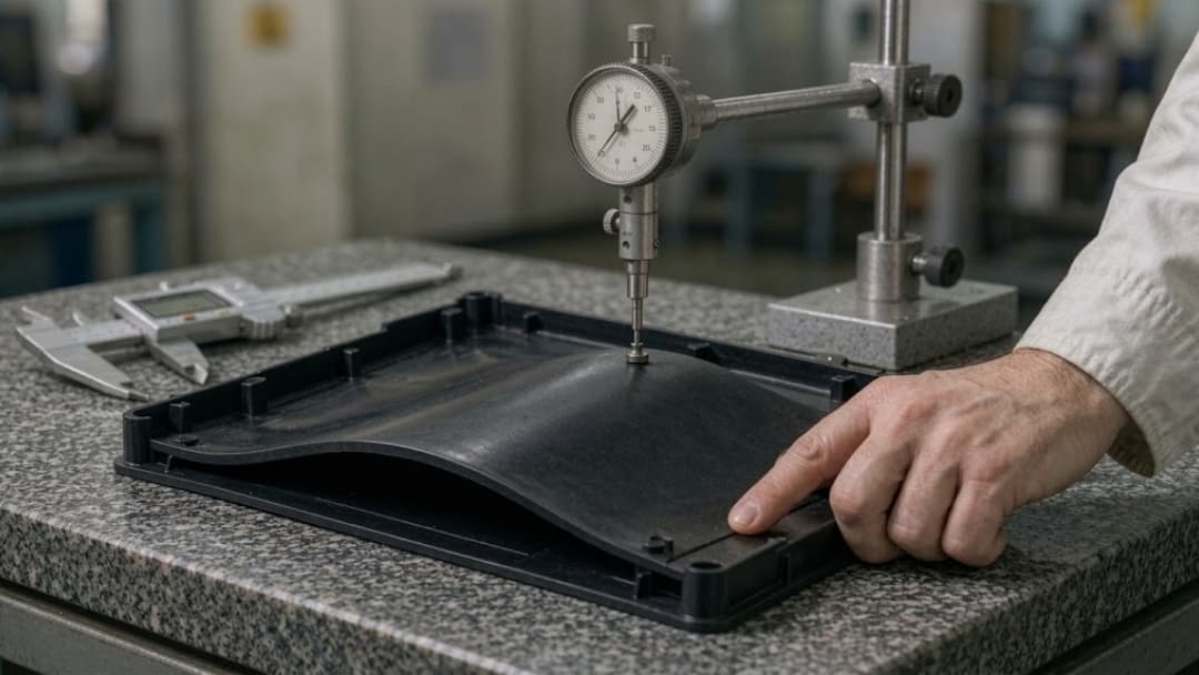
Warpage occurs when non-uniform volumetric shrinkage generates internal differential stresses across a molded component, causing it to twist or bow upon ejection.
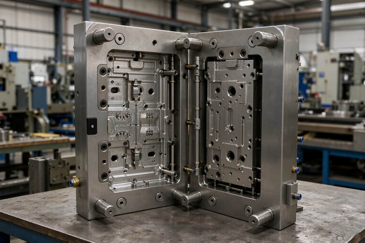
- Cooling Channel Layout: Non-uniform cooling rates between core and cavity mold halves drive thermal gradients. Tooling must incorporate conformal cooling lines or balanced water circuits to maintain uniform surface temperatures across both mold halves.
- Gate Location and Molecular Orientation: Polymers shrink more parallel to the flow direction than transverse to it, especially when using fiber-reinforced resins. Gates must be placed to promote unidirectional, balanced flow patterns across symmetrical features.
The Problem:
When melt flows into a part with non-uniform wall thickness or uneven cooling, it creates differential shrinkage across the part. This generates internal stress, which ultimately causes part warpage.
The Solution:
By designing uniform wall thickness and incorporating balanced cooling lines in the mold, shrinkage becomes uniform across the part, resulting in a flat, dimensionally stable part.
3. Flash: Clamping Force, Parting Line, and Tooling Precision
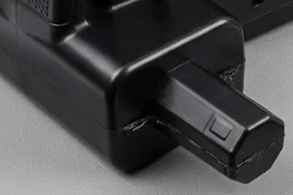
Flash consists of unwanted thin plastic films forced into the parting plane, slide interfaces, or around ejector pins during the high-pressure injection and holding phases.
- Clamping Force Verification: Ensure available press clamping tonnage exceeds total cavity projected area multiplied by average internal cavity pressure.
- Mold Machining Tolerances: Inadequate mold plate flatness, parting line deflection, or worn tool steel create micro-gaps. High-flow engineering plastics (such as PA66) require parting line shut-off tolerances matching the specific polymer’s flash threshold, which is typically tighter than general-purpose resins.
4. Short Shots: Flow Restriction, Venting, and Injection Pressure
A short shot occurs when the polymer melt solidifies before completely packing out the mold extremities.
- Flow Length-to-Thickness Ratio ($L/T$): If the flow path exceeds the material’s specific $L/T$ capability at the chosen nominal wall thickness, premature freeze-off occurs. Designers must increase wall thickness along long flow paths or relocate gates.
- Venting Provisions: Entrapped air inside blind pockets exerts backpressure, preventing melt entry and creating adiabatic compression burns (diesel effect). Machined perimeter vents, porous steel inserts, and ejector pin clearances must be placed at the final filling points.
- Prototype Validation: Verifying flow progression using rapid tooling injection molding helps pinpoint flow restrictions and vent locations before committing to high-volume production tooling.
5. Weld Lines: Melt Front Convergence and Temperature Control
Weld lines (knit lines) form when two or more flow fronts split around a core pin, hole, or multi-gate setup and recombine. If the melt fronts have cooled significantly, molecular entanglement remains incomplete, resulting in visible cosmetic lines and localized structural weakness.
- Gate Positioning: Position gates so that melt fronts converge in non-cosmetic, low-stress zones of the part.
- Thermal Control: Elevating mold surface temperatures or applying localized induction heating allows polymer chains to fuse thoroughly at the convergence interface.
How Engineering Plastics and Material Shrinkage Influence Molding Stability
Material selection fundamentally dictates the processing window and shrinkage behavior of molded parts. Polymer morphology determines how predictable tolerances will be throughout production.
- Amorphous Plastics (e.g., ABS, PC, PMMA): Feature random molecular arrangements, low and uniform volumetric shrinkage rates (typically 0.4%–0.7%), and higher dimensional stability, making them less prone to differential warpage.
- Semi-Crystalline Plastics (e.g., PA66, POM, PEEK, PP): Possess highly ordered molecular structures with higher shrinkage rates (typically 1.2%–2.5%). They require precise tool cooling controls and strict moisture management to prevent sudden dimension changes.
- Reinforced Resins: Adding glass or carbon fibers significantly reduces overall shrinkage along the flow direction while retaining higher transverse shrinkage, increasing the risk of part distortion if gating is not aligned with structural axes.
Processing advanced engineering plastic injection molding
grades requires verified material pre-drying, accurate resin viscosity data, and stable mold temperature controllers to maintain batch consistency.
Manufacturing Verification: Quality Control and Mold Precision Protocols
Preventing defects at scale requires transitioning from design theory to systematic shop-floor verification. A reliable injection molding OEM manufacturer
establishes quality gates throughout tool fabrication and part qualification.
The DFM-to-production workflow begins with a CAD/DFM review, where part geometry and rib/boss design are evaluated against manufacturability rules. This is followed by Moldflow analysis to simulate fill, pack, cooling, and warp—identifying potential defects before steel is cut. The tool is then fabricated using precision CNC and EDM techniques. After tooling completion, a T1 sample run is conducted under scientific molding setup to establish optimal process parameters. Parts are then verified through metrology and CMM inspection against CAD specifications, with continuous process monitoring ensuring ongoing quality throughout production runs.
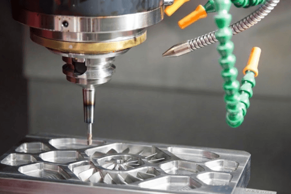
- Moldflow Simulation: Prior to steel cutting, digital mold flow simulations confirm gate locations, optimize cooling channel layouts, map predicted weld line positions, and identify air traps.
- Tooling Precision and Fit: High-precision CNC machining, wire EDM, and surface grinding ensure parting surfaces, slides, and lifters seat correctly without deflection under full clamping force.
- Scientific Molding Principles: Decoupling the injection phase into distinct fill, pack/hold, and cool stages creates a repeatable process window independent of machine model variations.
- Metrology Verification: Utilizing CMM (Coordinate Measuring Machines) and optical profilometers documented under a comprehensive quality system verifies critical dimensions against 2D drawings. Advanced inspection systems supported by modern quality equipment ensure that root causes of dimensional non-conformances are isolated and corrected systematically under a verified continuous improvement framework.
Key Takeaways
- Root-Cause Prevention: Up to 80% of molding defects originate from part geometry and mold construction; addressing wall thickness, gate design, and draft during DFM prevents chronic production scrap.
- Uniformity is Essential: Maintaining uniform nominal wall thickness and balanced cooling circuit layouts represents the most effective defense against sink marks, internal voids, and warpage.
- Material-Specific Tooling: Semi-crystalline and fiber-reinforced resins require custom shrinkage calculations, specialized gate locations, and precise thermal control compared to amorphous polymers.
- Closed-Loop Quality: True defect prevention combines digital Moldflow simulation, precision custom mold manufacturing, scientific process controls, and rigid CMM dimensional verification.
Frequently Asked Questions (FAQ)
Can all injection molding defects be fixed by adjusting machine settings?
No. Machine parameter adjustments (such as pack pressure, injection speed, or melt temperature) can optimize the process window for minor cosmetic flaws, but they cannot overcome fundamental tooling or part design errors such as severe non-uniform wall thickness, missing vents, or improperly positioned gates.
When is Moldflow analysis necessary during the tooling design phase?
Moldflow analysis is recommended for complex geometries, tight-tolerance components, multi-cavity tools, large surface parts, and whenever processing high-shrinkage or fiber-reinforced engineering plastics. It identifies fill imbalances, knit lines, and sink locations before cutting tooling steel.
What is the recommended rib-to-wall thickness ratio to prevent sink marks?
The base thickness of a reinforcing rib should generally be designed between 40% and 60% of the nominal wall thickness it attaches to, depending on the material’s specific shrinkage characteristics.
How does gate location influence part warpage?
Gate location determines the flow path, pressure distribution, and molecular orientation of the polymer. Uneven flow lengths or unaligned fiber orientation create differential shrinkage rates across the part, leading to residual internal stresses and warpage upon cooling.
How does GoodTech protect client intellectual property during DFM and manufacturing?
GoodTech operates under strict Non-Disclosure Agreements (NDAs), maintaining secure data handling protocols, restricted-access CAD/CAM servers, and closed internal workflows to protect proprietary component designs throughout DFM evaluation, tooling fabrication, and production.
Contact Us
Eliminate Molding Defects Before Production: Partner with GoodTech
Are you refining a new plastic part design or struggling with persistent defects and high scrap rates in your current production run? GoodTech’s engineering team provides thorough Design for Manufacturability (DFM) reviews, tooling feasibility analyses, and precision mold manufacturing to ensure stable, defect-free production.
Submit your 2D drawings and 3D CAD models (STEP/IGES) today to receive a comprehensive DFM analysis, moldflow assessment, and tooling evaluation from our technical team.Request a DFM Review & Tooling Consultation