
Plastic injection molding is a high-volume manufacturing process that melts a thermoplastic or thermoset material and injects it under pressure into a steel or aluminum mold cavity, where it cools and solidifies into a finished part. It is the standard choice for producing precise, repeatable plastic components at scale—from a single enclosure to millions of identical parts. This guide walks through how the process works, the main process variants, how to choose a material, the design rules that keep parts moldable, the defects you are most likely to meet, and what to check before you select a supplier. For the complete engineering parameters and a DFM checklist, see our injection molding design guide.
Our plastic injection molding services cover thermoplastic molding, overmolding, insert molding, two-color molding, and liquid silicone rubber (LSR), supported by in-house mold fabrication and a quality system built for medical, automotive, consumer electronics, and food-equipment applications.
How Injection Molding Works
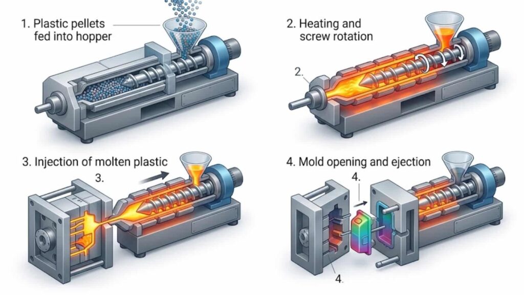
Injection molding runs in two connected phases: tooling and production.
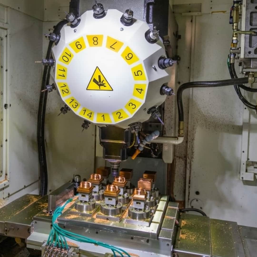
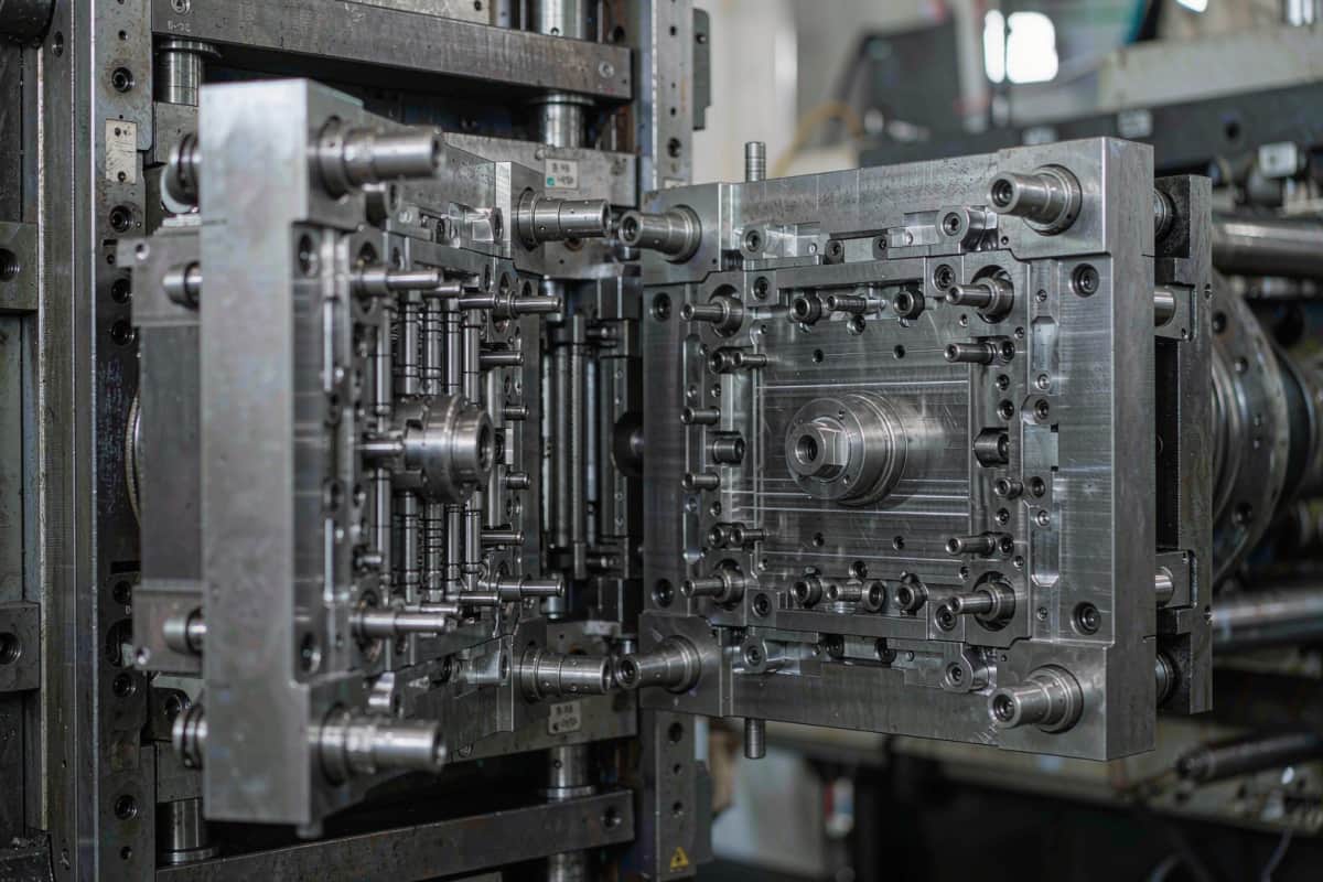
Phase 1 — Tooling. A mold is designed and built to the part geometry. The mold contains the cavity (the part shape), the runner and gate system that deliver melt to the cavity, cooling channels, and the ejection system. Good tooling decisions—steel choice, cooling layout, gate location—determine part quality and how consistently that quality holds across the full production run.
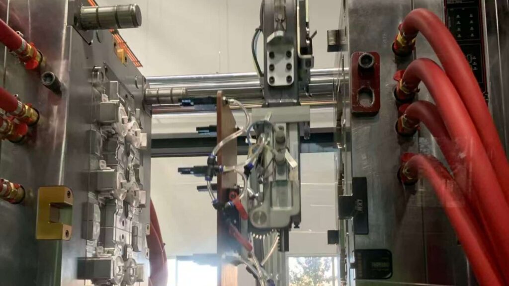
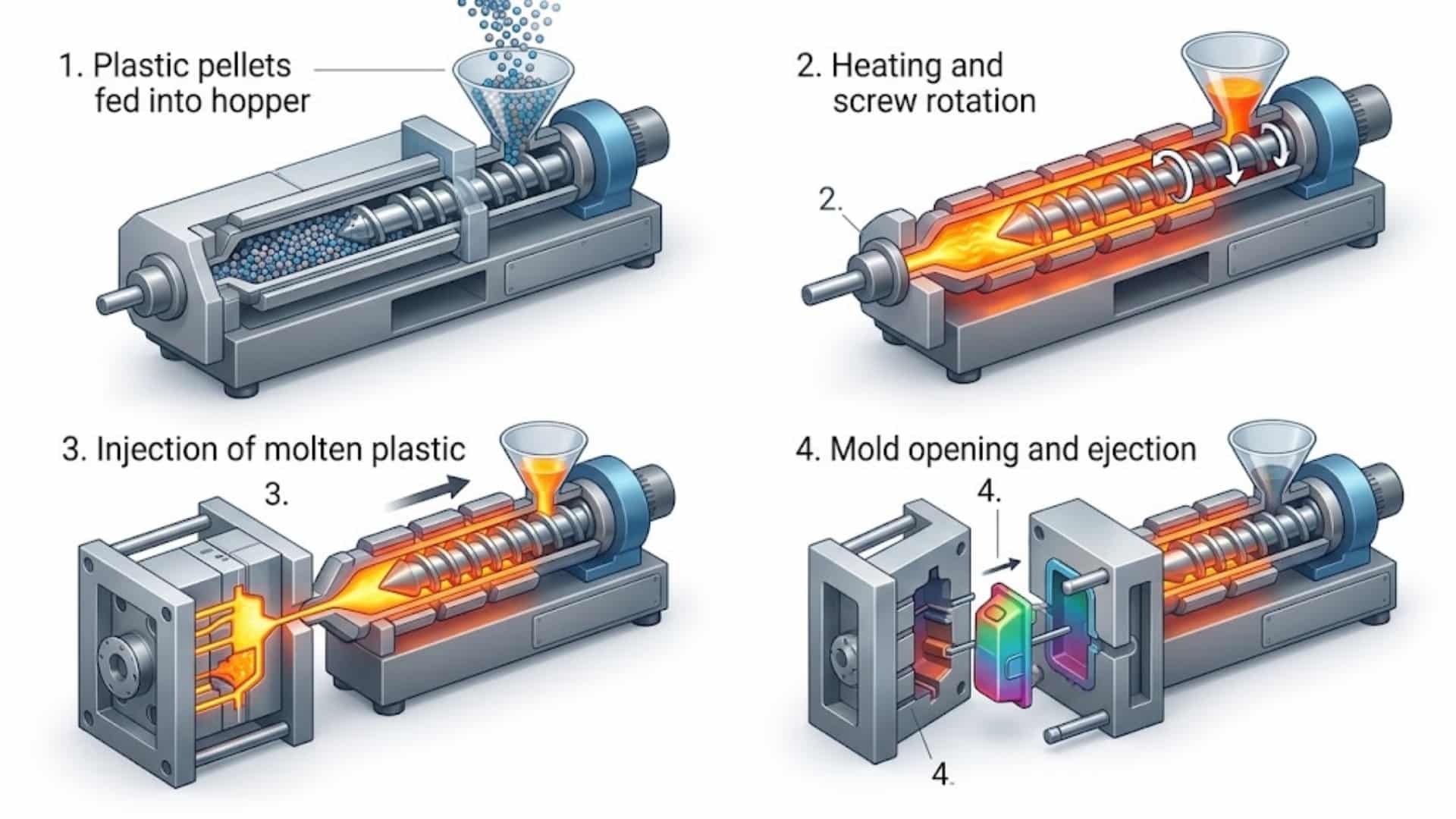
Phase 2 — Production cycle. Each shot repeats the same sequence:
- Clamp. The two mold halves close and lock under tonnage rated to the projected part area and material pressure.
- Inject. The plasticizing unit melts and pushes the material through the nozzle, runner, and gate into the cavity.
- Pack and hold. Additional material is packed in to compensate for shrinkage as the part cools.
- Cool. The part solidifies in the cavity; cooling time is usually the largest share of the cycle.
- Eject. The mold opens and pins or sleeves push the finished part out.
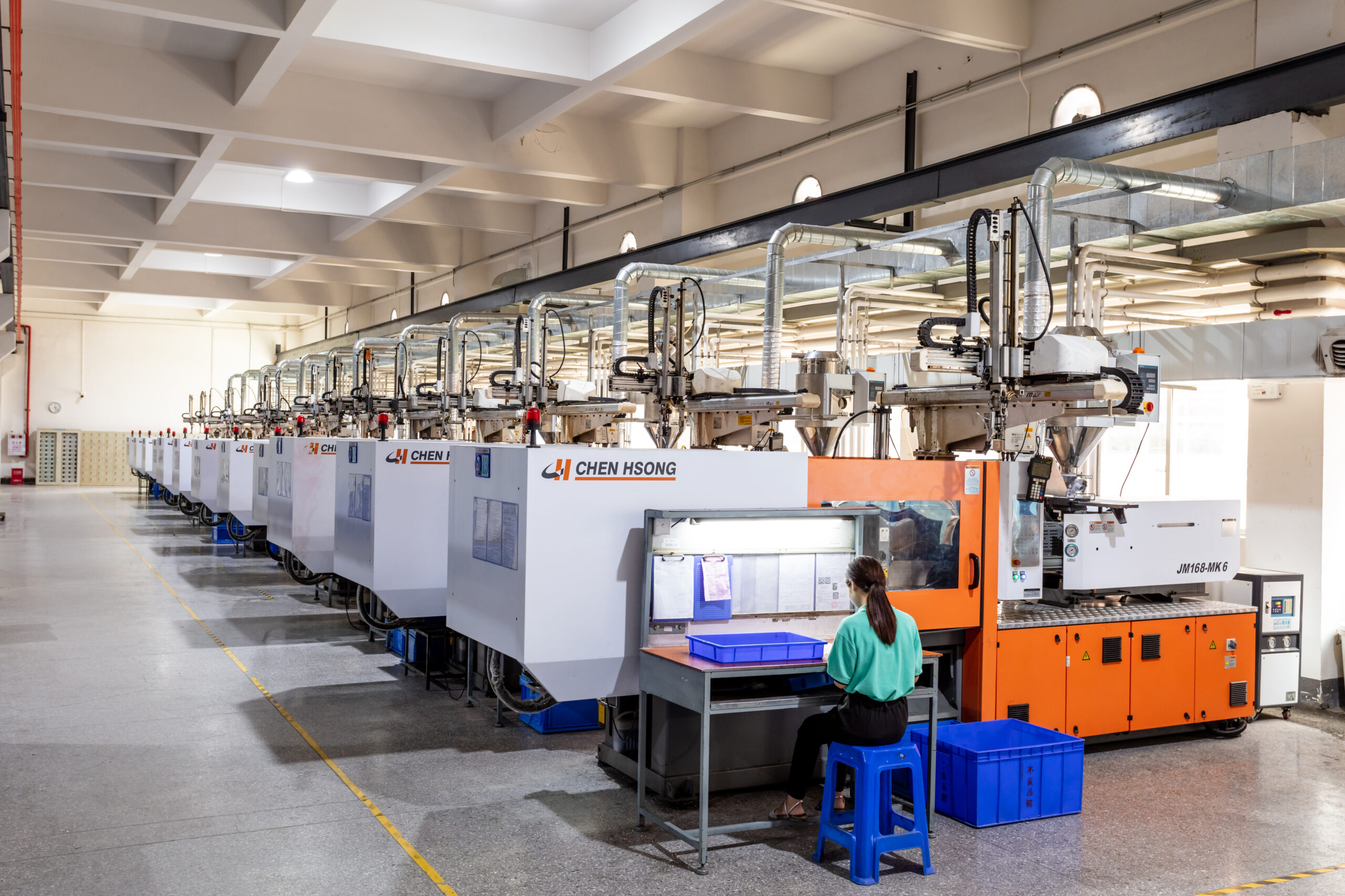
Machine tonnage typically ranges from small presses for miniature parts to large presses for automotive and structural components—our floor runs 60 to 1,000 tonnes, covering part weights from about 0.2 g to 4,500 g. Cooling rate, melt temperature, and mold temperature all influence dimensional stability, warpage, and surface appearance, which is why design and tooling are decided together rather than after the fact. Running a mold flow analysis before cutting steel helps catch fill, weld-line, and warpage risks early.
Types of Injection Molding
Different part requirements call for different process variants. The table below maps the most common ones to where they fit—and where they do not.
| Process | Best for | Key design note | Not ideal for |
|---|---|---|---|
| Thermoplastic injection molding | High-volume rigid or semi-rigid parts in ABS, PC, PA, POM, etc. | Uniform wall thickness, draft on all vertical faces | Very soft or liquid-state materials |
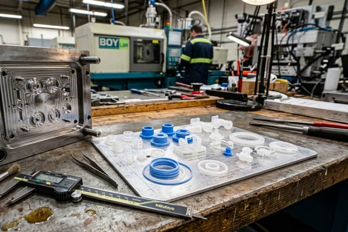
| LSR (liquid silicone rubber) molding | Flexible, heat-stable, biocompatible seals and gaskets | Cold-runner tooling, self-degating; see our LSR guide | Rigid structural parts |
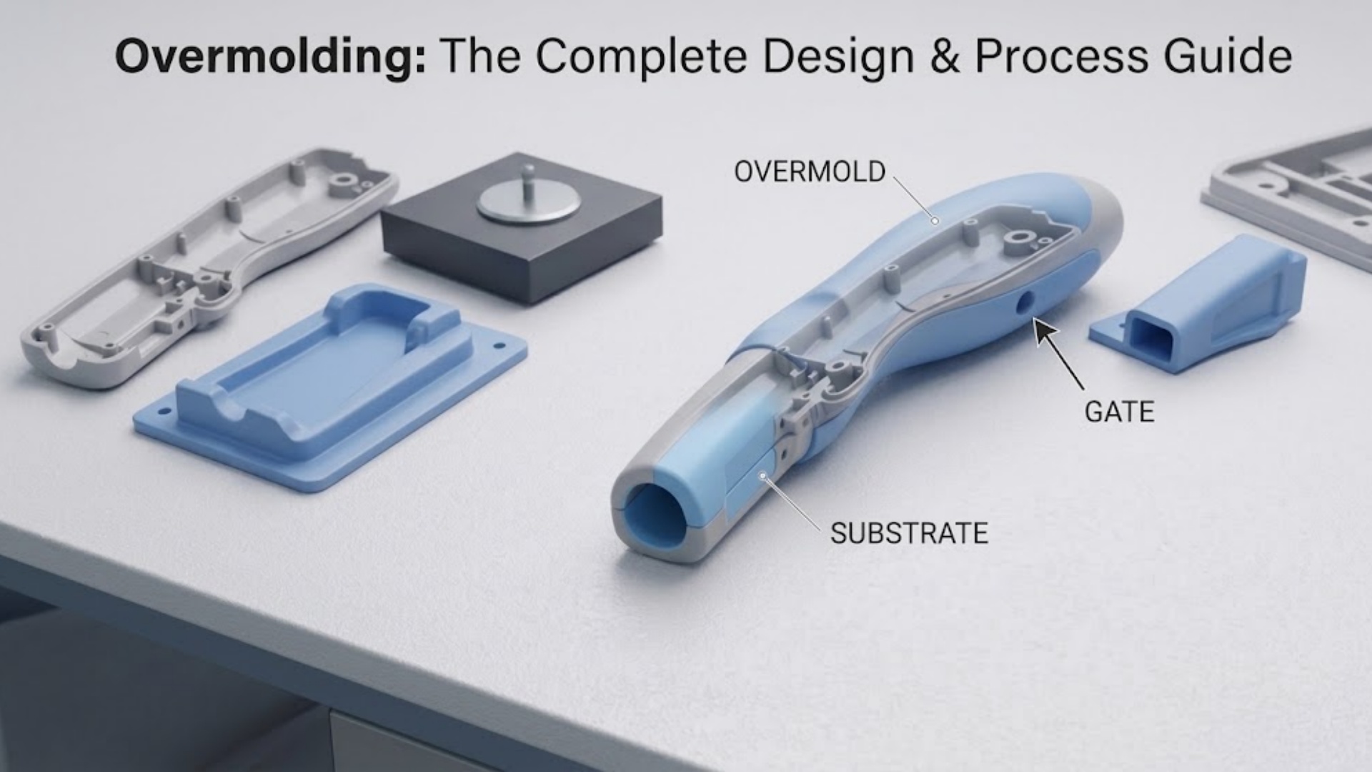
| Overmolding | Soft-grip handles, seals bonded to a substrate | Material compatibility and mechanical interlock; full detail in our overmolding guide | Parts needing two incompatible, non-bonding resins |
| Insert molding | Metal threads, bushings, or contacts molded into plastic | Secure the insert; avoid flow washing it out of position | High-cavitation runs where insert loading slows the cycle |
| Two-color (2K) molding | Sealed dual-material parts in one cycle | Gate and rotary/transfer tooling design | Simple single-material parts (adds cost) |
| Family / multi-cavity molding | Several related parts in one shot | Balance fill across cavities | Parts with very different wall thickness or volume |
| Reaction injection molding (RIM) | Large, low-volume, low-pressure urethane parts | Chemical cure vs. melt cooling; compare in our RIM vs. injection molding guide | Tight-tolerance, high-volume thermoplastic parts |
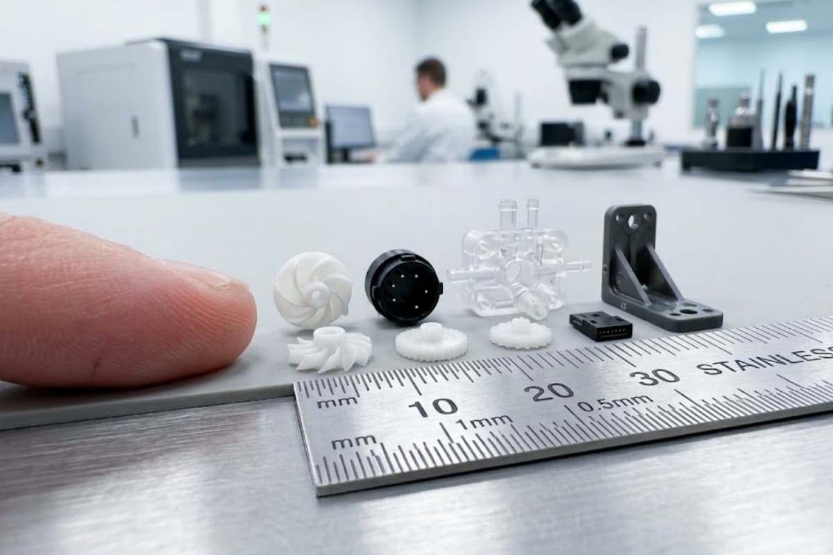
For miniature parts with tight tolerances, see our micro injection molding guide.
Injection Molding Material Selection
Materials fall into a few broad tiers. Pick by the combination of mechanical load, temperature, chemical exposure, appearance, and cost.
| Tier | Examples | Typical use | Watch out for |
|---|---|---|---|
| Commodity plastics | PP, PE, PS, ABS | Housings, containers, low-stress parts | Lower heat and chemical resistance |
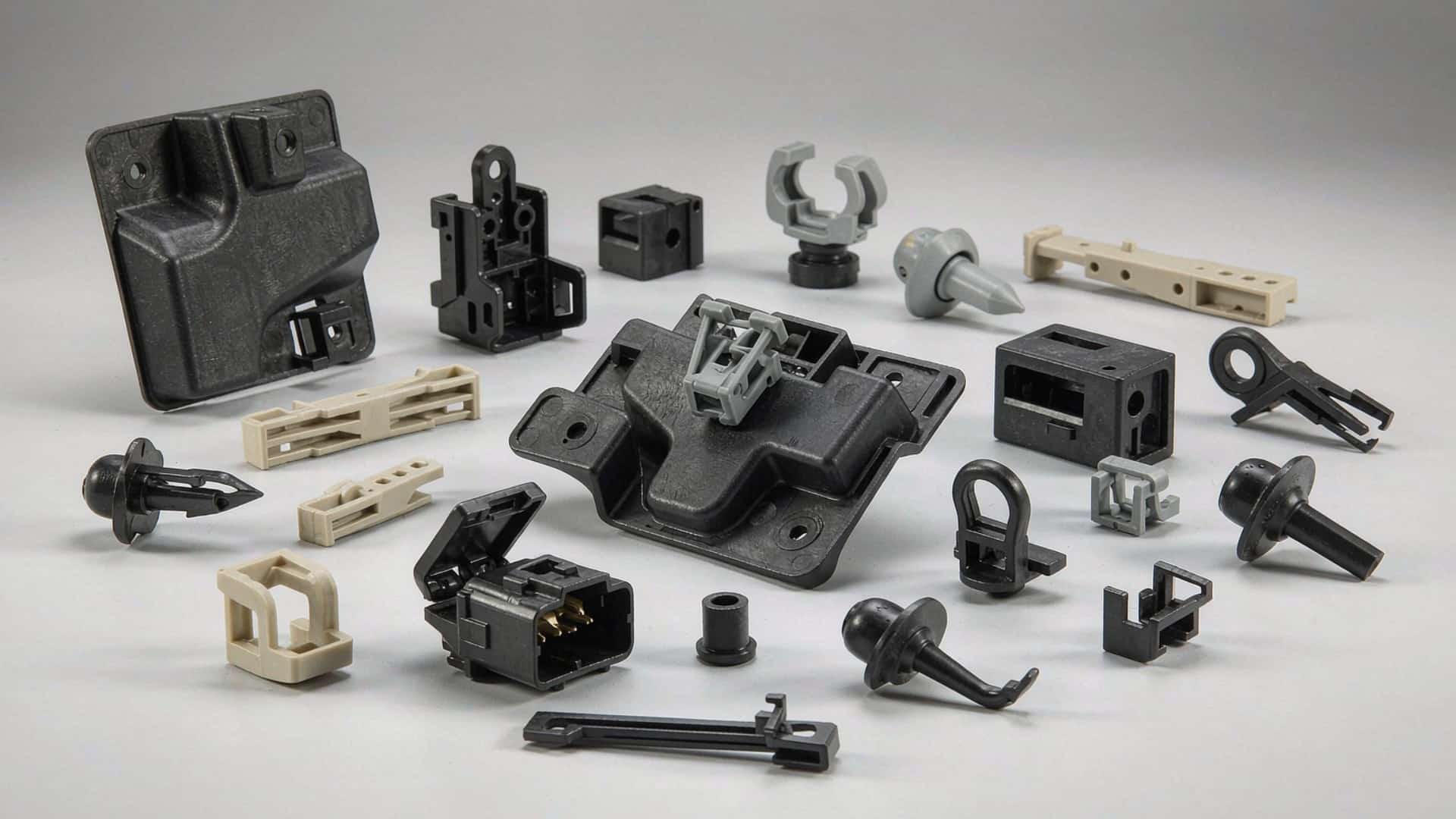
| Engineering plastics | PA (nylon), POM, PC, PBT | Gears, clips, structural brackets | Moisture absorption (PA), notch sensitivity (PC) |
| High-performance plastics | PEEK, PPS, PEI | Under-hood, medical, aerospace | Higher material and processing cost |
| Elastomers (TPE/TPU) | TPU, TPE blends | Soft grips, seals, gaskets | Compression set, bond strength in overmolding |
| Silicones (LSR) | Liquid silicone rubber | Medical seals, food-contact parts | Different tooling and curing than thermoplastics |
Choosing by application:
- Medical and lab devices demand documented materials and traceability. Our medical injection molding work uses biocompatible resins and clean-process controls under ISO 13485.
- Automotive parts need heat, chemical, and fatigue resistance; our automotive plastic injection molding page covers resin and supplier considerations for the sector.
- Consumer electronics prioritize dimensional precision, thin walls, and surface finish.
- Food equipment needs compliant, cleanable materials and stable geometries.
Exact shrinkage and mechanical values vary by grade and filler, so confirm the specific resin data sheet with your molder before locking tolerances. For engineering-resin deep dives, the design guide referenced above is the place to start.
Injection Molding Design Tips (DFM Overview)
Design for manufacturing (DFM) is what turns a 3D model into a part that fills completely, ejects cleanly, and holds dimensions. The essentials:
- Keep wall thickness uniform. Sudden thick-to-thin transitions cause sink and voids. Where a change is unavoidable, blend it gradually.
- Add draft (taper) to every vertical face. Typical draft is 1–2°; textured surfaces need more. Draft is what lets the part release from the cavity without scraping.
- Size ribs and bosses carefully. Ribs are usually a fraction of the adjacent wall so they do not sink; bosses need their own support.
- Use generous fillets. Rounding internal corners reduces stress concentration and improves fill.
- Place gates and ejector pins where they will not show or weaken the part. Gate location drives weld lines and flow balance.
- Avoid unnecessary undercuts. Each undercut can mean a side-action or hand-loaded insert that adds tooling cost and cycle time.
This is an overview. For the full parameter ranges, worked examples, and a downloadable checklist, see our dedicated injection molding design guide.
Designing Complex Features
A few features come up constantly in real parts:
- Clips and snap fits rely on material resilience. Pick a resin with enough flexural recovery and size the beam so it does not yield on assembly.
- Living hinges work best in polypropylene, cut thin and uniform so the molecule chain orients across the hinge.
- Bosses and standoffs should be cored (hollowed) and supported by ribs or gussets to avoid sink on the outside wall.
- Molded text and logos need enough size and depth to read after molding and ejection; keep them on a flat, draft-equipped surface.
- Overmolding bonds a second material to a substrate. Success depends on chemical compatibility or a mechanical interlock geometry—our overmolding design guide covers both.
Common Injection Molding Defects and Design Fixes
Most defects trace back to design or tooling, not the machine. The table maps the usual suspects to their likely design cause and fix.
| Defect | What it looks like | Common design cause | Design fix |
|---|---|---|---|
| Sink marks | Dents over thick areas | Localized thick sections, slow pack | Reduce wall/thickness, add ribs, improve gate location |
| Warpage | Part twists or bows | Uneven shrinkage, asymmetric walls | Uniform walls, balanced fill, symmetric ribs |
| Voids / porosity | Internal holes, weak spots | Trapped gas or shrinkage in thick zones | Thinner sections, venting, higher pack pressure |
| Flash | Thin fin at parting line | Over-pack, weak shutoff | Tighten shutoff, reduce pack, fix tooling |
| Short shot | Incomplete fill | Thin walls far from gate, slow fill | Thicker walls, better gate placement, more vents |
| Flow / jetting marks | Snake-like or streaky surface | Melt hitting a wall directly at the gate | Relocate gate, add overlap or fan gate |
Where the root cause is a design rule, the DFM guide explains the underlying principle so the fix sticks.
Surface Finishes and Post-Processing
Molded parts leave the tool with a finish set by the cavity surface: non-cosmetic, low-gloss, polished, or textured (bead-blast or etched). Textured and etched surfaces need extra draft so the part releases. Beyond the mold finish, secondary operations add function and appearance:
- Printing—screen and pad printing for labels and marks
- Painting and coating for color, abrasion, or chemical resistance
- Surface transfer—water-transfer and heat-transfer decoration
- Shielding and assembly for electronic and multi-part products
Our plastic injection molding and mold fabrication pages describe how finish and texture are built into the tool.
Quality Control and Certifications
For production parts, quality is a system, not an inspection at the end. Our programs run on documented controls:
- ISO 9001 – general quality management
- IATF 16949 – automotive quality management
- ISO 13485 – medical device quality management
- ISO 14001 – environmental management
- UL 746D – polymer materials for electrical equipment
Day-to-day we use FMEA, control plans, SPC, and PPAP, and for medical programs the IQ/OQ/PQ validation sequence. Incoming-material checks, in-process monitoring, and traceability close the loop. See the quality system page for the full scope.
Cost, Lead Time & Choosing a Supplier
Two cost pools matter. Tooling is a one-time investment that scales with complexity, size, and cavitation; per-part cost falls as volume rises because the tool is amortized and setup is spread across more pieces. Lead time depends on tool complexity, material approval, validation needs (especially medical and automotive), and any secondary operations. Exact figures should be confirmed with your molder against the specific part.
Before you commit, evaluate a supplier on:
- Engineering capability – Do they run DFM and mold-flow review up front? (See our design guide.)
- Certifications matched to your industry (ISO 13485 for medical, IATF 16949 for automotive).
- IP protection – NDA coverage and a clear data-handling policy before you share CAD.
- Secondary operations – printing, coating, shielding, and assembly under one roof reduce hand-offs.
- Communication – bilingual engineering support and responsive turnaround shorten design loops.
- Geography and tariff – a Vietnam production option can reduce landed cost for certain North American and international programs.
Before cutting steel, validate the design with rapid prototyping (CNC, 3D printing, or vacuum casting) to confirm fit, function, and assembly. Real examples of production work are in our case studies, including a thin-wall automotive cable-shielding part, an injection-molded electrical enclosure, a medical device screen frame, and a consumer-electronics enclosure.
Injection Molding Glossary
- Boss – A raised post or hub, usually for fastening or locating.
- Draft – The taper on a vertical face that lets the part release from the mold.
- Gate – The point where melt enters the cavity from the runner.
- Runner – The channel that carries melt from the nozzle to the gate.
- Shutoff – A mold surface where two halves meet to seal the cavity.
- Side-action – A sliding mold component that forms an undercut, then retracts.
- Undercut – A feature that prevents straight ejection without a side-action.
- Sink mark – A surface depression caused by internal shrinkage.
- Weld line – A visible line where two flow fronts meet.
- Tonnage – The clamping force of the machine, matched to part size and material.
- Cavity – The shaped space in the mold that defines the part.
- Ejector pin – A pin that pushes the finished part out of the mold.
Frequently Asked Questions
What makes a part suitable for injection molding?
A geometry with mostly uniform wall thickness, draft on vertical faces, no unnecessary undercuts, and volume high enough to justify tooling. Very low volumes may be better served by prototyping or RIM.
How can I reduce injection molding cost?
Design for uniform walls to cut material and cycle time, avoid undercuts that need side-actions, consolidate parts through overmolding or insert molding, and validate with prototyping before tooling. Tooling cost is fixed, so per-part cost drops with volume.
What causes warpage?
Uneven shrinkage from asymmetric walls, poor gate balance, or inadequate cooling. Keep walls uniform, balance fill, and let the tool designer place cooling and gates deliberately.
How much draft angle do I need?
Typically 1–2° on vertical faces; textured or etched surfaces need more. The DFM guide covers draft by feature and finish.
When should I use insert molding instead of overmolding?
Use insert molding when a rigid component (metal thread, contact, bushing) is placed in the mold and plastic forms around it. Use overmolding when a second plastic or elastomer is bonded onto a molded substrate for grip or sealing.
How long does tooling and production take, and what does it cost?
It depends on part complexity, size, material approval, and validation requirements. Confirm specifics with your molder; do not rely on generic figures.
How do I choose a supplier?
Check engineering depth (DFM, mold flow), industry certifications, IP/NDA protection, in-house secondary operations, and communication. Review our case studies and quality system as a starting point.
How is my design protected?
Share CAD only under a signed NDA and confirm the supplier’s data-handling policy up front. Our contact page is where you start that conversation.
Feel free to contact the GoodTech technical team
Injection molding rewards good decisions made early: the right process, the right material, and a design built around uniform walls, draft, and clean ejection. Use this guide as the map, and use the linked deep-dive pages—DFM, materials by industry, and process variants—when you need specifics.
When your design is ready for a manufacturing review, request a DFM review under NDA and our engineering team will check moldability, suggest tooling and gate strategy, and outline a path from prototype to production.