
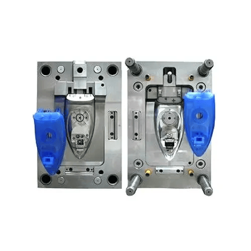
Precision injection moulding is a specialised manufacturing methodology engineered to produce complex plastic components with tight dimensional tolerances—typically within ±0.01 mm to ±0.02 mm. Achieving this level of dimensional repeatability requires synchronising four core technical pillars: tool design governed by strict Design for Manufacturability (DFM) rules, scientific in-cavity process control, advanced polymer selection, and metrology-backed quality verification.
This technical guide details the critical design standards, dynamic processing parameters, tooling considerations, and material characteristics necessary to manufacture high-precision, defect-free polymer components for demanding industrial and engineering assemblies.
1. Fundamentals of Precision Injection Moulding: Beyond Standard Processing
Standard plastic injection moulding prioritises rapid cycle times and cosmetic consistency across commercial products with standard dimensional tolerances (±0.1 mm to ±0.2 mm). In contrast, precision moulding focuses on micron-level dimensional stability, minimal internal residual stress, and structural isotropy.
Precision Moulding Pillars
| Pillar | Description |
|---|---|
| 1. High-Rigidity Tooling | Hardened tool steels, sub-micron machining, balanced thermal cooling channels, and micro-venting. |
| 2. Scientific Moulding | Decoupled processing, in-cavity pressure transducers, dynamic viscosity tracking, and closed-loop control. |
| 3. High-Grade Polymers | Tight batch-to-batch MFI control, predictable shrink rates, and optimized crystallinity behavior. |
| 4. In-Line Metrology | Statistical process control (Cpk ≥ 1.33), CMM verification, and First Article Inspection Protocols. |
Achieving high-tolerance stability requires understanding the interaction between melt flow dynamics, volumetric shrinkage, and cavity pressure transitions throughout each moulding cycle.
2. Core DFM Guidelines for Precision Plastic Mould Fabrication
Implementing robust Design for Manufacturability (DFM) principles early in the engineering phase mitigates the primary causes of mould failure, warpage, and post-moulding shrinkage.
Wall Thickness Uniformity and Core-Out Strategies
Uneven wall thickness induces differential cooling rates across the part geometry. Thicker regions cool slower than adjacent thin walls, creating localised volumetric contraction that leads to sink marks, internal voids, and residual stress.
- Nominal Wall Uniformity: Maintain consistent wall thickness across the component. When transitions are unavoidable, incorporate gradual tapers (maximum thickness variation should not exceed 15% to 25%).
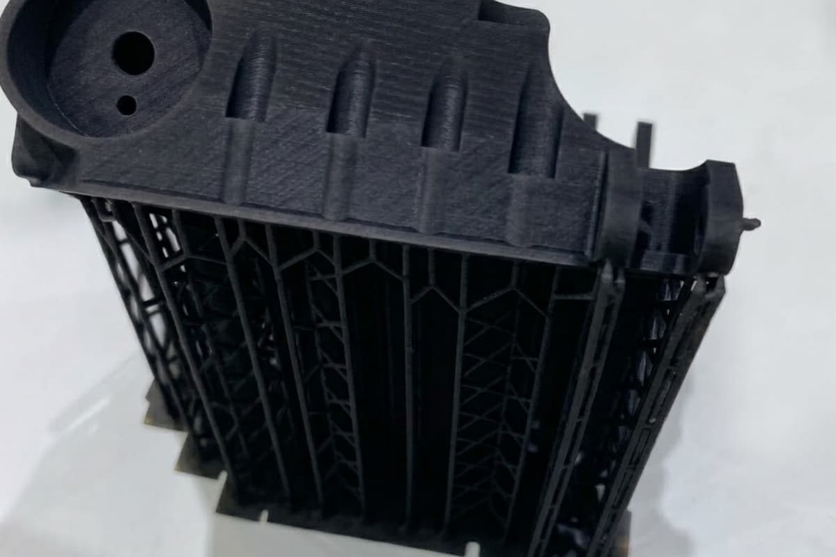
- Coring Out Heavy Sections: Remove solid mass from thick cross-sections, ribs, and intersections by coring out material, replacing bulky profiles with supported thin-wall networks.
Precision Draft Angles and Parting Line Architecture
Draft angles facilitate clean component release from tool cavities without scuffing, drag marks, or distortion caused by ejection forces.
- Smooth Finishes (SPI A1–A3): Specify a minimum of 0.5° to 1.0° of draft per side.
- Textured Surfaces (VDI 3400 / Mold-Tech): Add an additional 1.0° to 1.5° of draft for every 0.025 mm (0.001 in) of texture depth.
- Parting Line Placement: Align parting lines along primary part edges to eliminate visible witness lines on critical mating surfaces and avoid flash generation along functional dimensions.
Structural Ribs, Bosses, and Gussets
Reinforcing features add mechanical stiffness without increasing the nominal wall thickness.
- Rib Proportions: Keep rib base thickness between 40% and 60% of the adjacent nominal wall thickness. Limit rib height to less than three times the nominal wall thickness.
- Screw Boss Geometry: Core out the base of screw bosses to the nominal wall thickness to avoid material accumulation. Add external gussets to reinforce tall, freestanding bosses.
Gating Strategy, Runner Balance, and Complex Undercuts
The mould gating system dictates melt velocity, fiber orientation, and the position of weld lines.
- Sub-Gates and Edge Gates: Position gates at the thickest structural section, allowing plastic to flow from thick areas toward thinner features.
- Balanced Runner Systems: Use naturally balanced hot or cold runner networks to equalize cavity fill times and packing pressures across multi-cavity tools.
- Undercut Tooling Mechanisms: Resolve complex lateral features using mechanical slide-actions, angular lifters, or collapsible cores during custom mould manufacturing.
DFM Feature Targets
| Feature | Precision Target Rule | Potential Failure if Ignored |
|---|---|---|
| Nominal Wall | Uniform within ±10%; blend transitions. | Differential shrinkage, structural warpage |
| Rib Base Thickness | 40%–60% of nominal wall | Sink marks on opposing cosmetic surfaces |
| Draft Angle | 0.5°–1° (polished), 1.5°–3°+ (textured) | Drag marks, deformation during ejection |
| Boss Base Thickness | 25%–50% of base wall via coring | Deep sink marks, core pin bending |
| Radius Fillets | 0.5 × nominal wall (min 0.5 mm) | High stress concentrations, brittle impact failure |
3. Scientific Moulding & Advanced In-Cavity Process Control
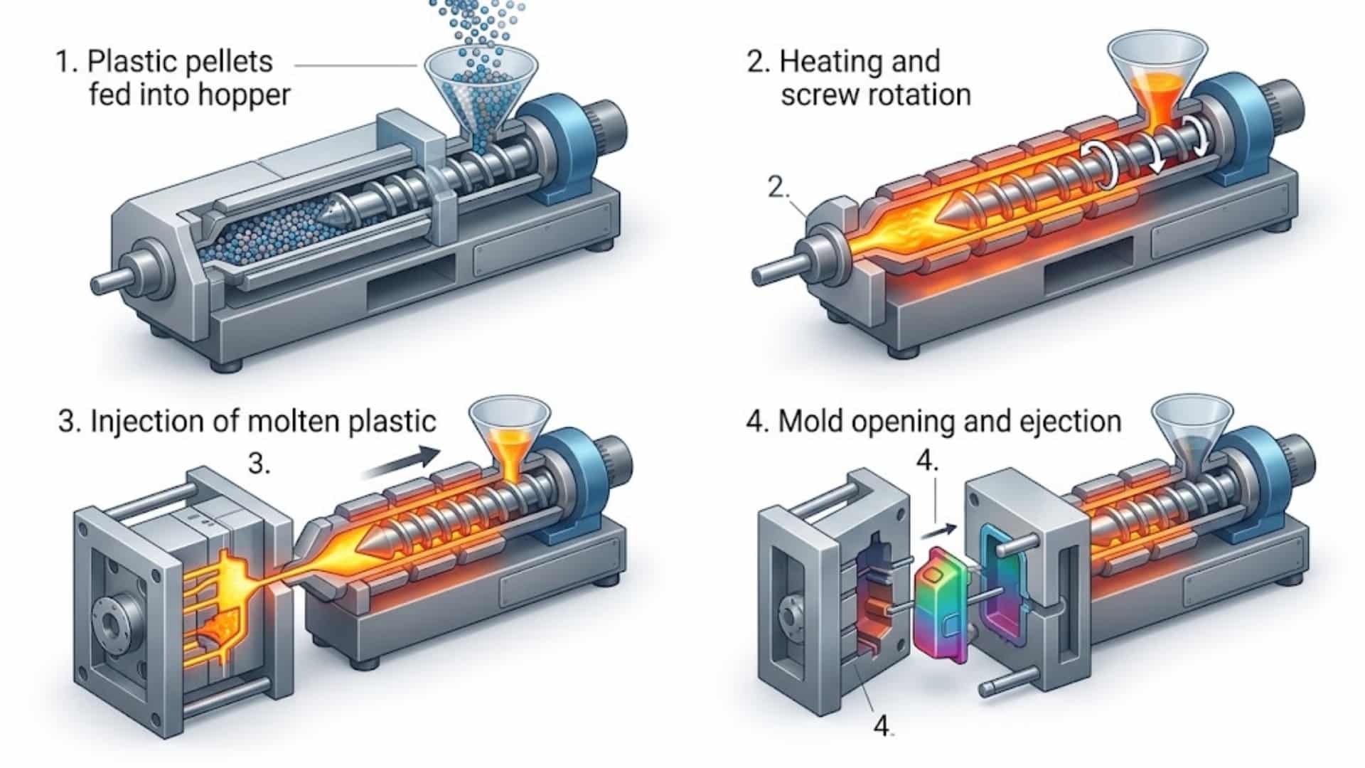
Conventional moulding relies on machine-set parameters (hydraulic pressure, barrel temperatures, timer settings) that fluctuate as raw material batches vary. Scientific moulding decouples the process into independent, measurable physical stages governed by real-time in-cavity melt behaviour.
Decoupled Moulding Methodology
- Stage 1: Fast Fill (95–98% Volume) – Controlled by Injection Velocity
- Stage 2: Pack & Hold (2–5% Volume) – Governed by Cavity Pressure Transducers
- Stage 3: Dynamic Cooling & Solidify – Balanced Water Line Heat Dissipation
- Stage 4: Part Ejection – Synchronised Multi-Pin Hydraulic Force
Stage 1 (Volumetric Fill): The machine fills 95% to 98% of the cavity under strict velocity control, bypassing pressure limits to maintain a consistent shear rate and viscosity profile.
Stage 2 (Pack and Hold): As the cavity nears full volume, the machine switches via a precise V/P (Velocity-to-Pressure) transfer position to pressure-controlled packing. This stage compensates for polymer volumetric shrinkage until the gate solidifies.
Stage 3 (Thermal Cooling): Conformal cooling channels maintain uniform temperature across core and cavity inserts, dissipating heat evenly to prevent internal stresses and anisotropic warpage.
Stage 4 (Controlled Ejection): Balanced multi-point ejector systems release the solidified part without applying bending moments or mechanical strain to tight-tolerance features.
Integrating in-cavity pressure and temperature sensors allows engineering teams to practice systematic continuous improvement, monitoring Viscosity Index, Peak Cavity Pressure, and Energy Consumption across every cycle to isolate dimensional drifts.
4. High-Performance Engineering Polymers: Selection and Moulding Characteristics
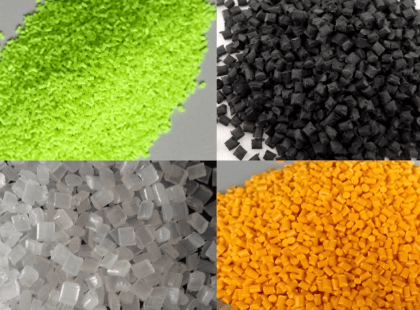
Selecting the proper thermoplastic resin requires balancing mechanical load capabilities, continuous operating temperatures, chemical resistance, and specific shrinkage properties.
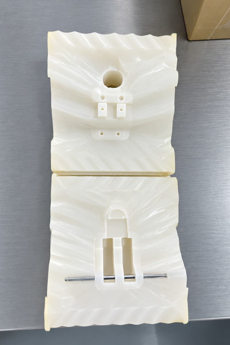
Before committing to production tooling, verifying fit and mechanical behavior via functional rapid prototyping validates resin selection under simulated working environments.
| Polymer Family | Continuous Service Temp (°C) | Typical Shrinkage Rate (%) | Processing Highlights & Mould Considerations | Key Industrial Applications |
|---|---|---|---|---|
| PEEK (Polyetheretherketone) | Up to 250 | 1.0–1.5 (Unfilled) | Requires high mould temps (160–200°C) to achieve full semi-crystalline properties and chemical resistance. | Precision gears, aerospace connectors, industrial pump components |
| PPS (Polyphenylene Sulfide) | Up to 200 | 0.2–0.6 (GF-Reinforced) | High dimensional stability, low moisture absorption; abrasive fillers require hardened tool steels (e.g., H13, S136). | Automotive sensor housings, electrical terminal blocks, fluid systems |
| PEI (Polyetherimide / Ultem) | 160 – 180 (typical 170) | 0.5–0.7 (Amorphous) | High dielectric strength, inherent flame resistance; requires thoroughly dried resin and high injection pressures. | High-voltage electrical isolators, structural brackets |
| POM (Polyoxymethylene / Acetal) | Up to 90 | 1.8–2.5 (High Shrink) | High lubricity, low friction coefficient, excellent creep resistance; sensitive to uniform wall thickness and cooling balance. | Precision bearings, sliding bushings, mechanical gears |
| PA66 + 30% GF (Polyamide + Glass) | 100 – 130 (typical 110) | 0.3–0.8 (Anisotropic) | Glass fiber alignment causes differential shrinkage (parallel vs. perpendicular); requires optimized gate placement. | Heavy-duty structural housings, industrial manifolds |
5. Precision Tooling Manufacturing & Quality Assurance Standards
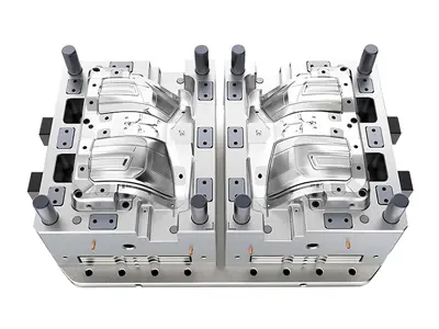
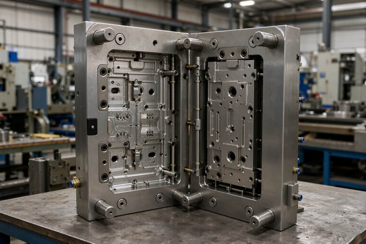
The ultimate precision of a moulded part is constrained by the precision of the injection mould. Achieving micron tolerances requires specialised tooling fabrication equipment, hardened tool steels, and closed-loop inspection processes.
Tool Fabrication & Metrology Workflow
- High-Speed CNC Milling: Hardened cores & cavities machined to <= ±0.005 mm
- Mirror EDM & Wire EDM: Sub-micron spark erosion for complex ribs & vents
- In-Process CMM Checks: Coordinate measuring verification of tool inserts
- First Article (FAIR): Full GD&T inspection before serial production run
- Statistical Cpk Analysis: Continuous verification ensuring process Cpk >= 1.33
Advanced Toolroom Technologies
- High-Speed CNC Milling (30,000+ RPM): Produces complex 3D contours on hardened mould inserts with tolerances within ±0.005 mm.
- Mirror Spark Erosion (EDM) & Slow-Feed Wire EDM: Machines narrow slots, sharp internal corners, and micro-ribs without introducing mechanical stress.
- Mould Steel Selection: Utilizing hardened stainless steels (e.g., S136, 50–54 HRC) resists corrosive resin outgassing and prevents cavity wear during long production runs.
Metrology & Inspection Protocols
To confirm precision tolerances across multi-cavity runs, manufacturers adhere to an ISO-aligned quality management system.
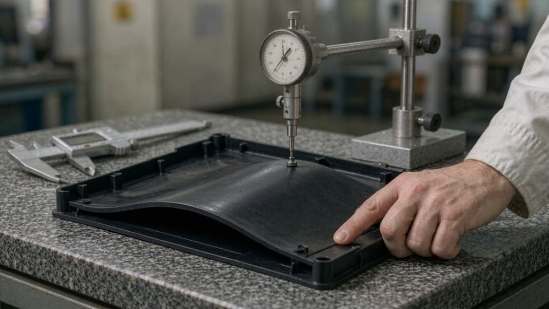
Inspection teams utilize advanced metrology equipment, including Bridge Coordinate Measuring Machines (CMM), optical video measurement systems, and multi-sensor laser scanners to verify tight Geometric Dimensioning and Tolerancing (GD&T) callouts.
- First Article Inspection Reports (FAIR): Verifies every critical print dimension on initial parts off the tool.
- Process Capability Index (Cpk): Evaluates dimensional repeatability across sample lots, maintaining Cpk ≥ 1.33 for standard features and Cpk ≥ 1.67 for critical mating dimensions.
6. Common Precision Moulding Defects: Root Causes & Tooling Solutions
Eliminating defects in precision components requires systematic problem-solving that addresses both tool geometry and dynamic processing parameters.
| Defect | Root Cause Mechanism | Tooling / DFM Corrective Action | Scientific Moulding Process Fix |
|---|---|---|---|
| Sink Marks | Localised volume shrinkage caused by slow cooling in thick sections. | Core out thick masses; reduce rib base thickness to 40%–60% of nominal wall. | Increase pack pressure; extend hold time past gate freeze-off. |
| Warpage & Bowing | Differential cooling rates or anisotropic shrinkage from fiber orientation. | Optimise cooling line placement; relocate gates to align fiber flow symmetrically. | Balance mould core-cavity temperature differential; decrease injection pressure. |
| Flash (Burrs) | Mould parting surfaces forced open by excessive cavity pressure or poor shut-off seal. | Re-grind parting line shut-offs; increase mould clamping tonnage; add support pillars. | Lower pack pressure; advance V/P switchover position earlier. |
| Short Shots | Premature melt freeze-off or trapped air pockets obstructing flow paths. | Enlarge runner/gate diameters; machine perimeter air vents (0.015–0.025 mm deep). | Increase injection speed; raise melt and barrel temperatures. |
| Weld Lines | Weak molecular bonding where converging melt fronts meet at lower temperatures. | Relocate gates to move weld lines to non-structural areas; add local flow tabs. | Elevate injection speed and mould temperature to boost weld front packing. |
7. Procuring Custom Injection Moulds: SPI Tooling Classification & Engineering Checklist
Choosing the right mould construction standard prevents tool under-engineering (leading to premature tool failure) or over-engineering (unnecessary capital investment).
| SPI Class | Rated Production Life | Steel Hardness | Recommended Application |
|---|---|---|---|
| Class 101 | 1,000,000+ Cycles | ≥ 48 HRC (Hard) | Extreme volume, high-speed |
| Class 102 | Up to 1,000,000 Cycles | 28–36 HRC (Pre-H) | Medium-high production |
| Class 103 | Up to 500,000 Cycles | P20 / Steel Core | Medium production volumes |
| Class 104 | Up to 100,000 Cycles | Pre-hard / Alum | Low-volume runs |
| Class 105 | Up to 500 Cycles | Cast / Soft Metal | Prototype validation only |
When requesting quotes for custom mould fabrication, provide a complete engineering data package to ensure an accurate technical assessment:
- 3D CAD Model: Clean .STEP or .IGES files with nominal geometry.
- 2D Technical Drawings: Complete .PDF drawings detailing critical dimensions, allowable tolerances, and GD&T datums.
- Resin Specification: Specific polymer trade name, grade, colorant, and filler percentage (e.g., PA66 30% GF).
- Expected Annual Usage (EAU): Total projected volume to determine the optimal number of cavities and SPI tooling class.
- Secondary Operations: Requirements for ultrasonic welding, insert pressing, surface printing, or cleanroom assembly.
8. Partnering with GoodTech: Engineering-Led Moulding Solutions & Global Support
Procuring precision plastic components requires a manufacturing partner that combines toolroom expertise with rigorous, documented quality systems. GoodTech delivers precision injection moulding solutions built around technical collaboration and dependable execution.
- Engineering-Driven Collaboration: Technical consultations directly with experienced tooling engineers to refine DFM parameters, evaluate mould flow simulations, and optimise cycle efficiencies.
- Intellectual Property Protection: Robust confidentiality infrastructure, comprehensive NDAs, and secure data storage to safeguard proprietary customer CAD designs and trade secrets.
- Rapid Turnaround & Response: Detailed DFM engineering reviews delivered within 24 hours, alongside structured project management to ensure tight delivery schedules.
- Seamless Cross-Cultural Communication: Bilingual project management teams bridging time zones, engineering standards, and international logistics.
To begin your next tooling or production project, contact our engineering team to receive a complete DFM design review and detailed tooling quotation.
Key Takeaways
- Micron-Level Tolerance Feasibility: Precision plastic injection moulding consistently achieves tolerances between ±0.01 mm and ±0.02 mm by integrating hardened steel tooling, scientific process control, and real-time in‑cavity sensing.
- Uniform Wall Thickness is Paramount: Non-uniform walls cause localised differential cooling, leading directly to sink marks, internal voids, and severe component warpage.
- Scientific Moulding Decouples Fill and Pack: Separating dynamic velocity fill (Stage 1) from pressure packing (Stage 2) insulates the process from raw resin viscosity variations across production batches.
- High-Performance Polymers Require High Mould Temperatures: Semi‑crystalline engineering plastics such as PEEK and PPS demand elevated mould temperatures (150°C to 200°C) to achieve full crystallisation and peak mechanical strength.
- Data-Driven Quality Validation: Validating critical tolerances requires rigorous statistical process control (Cpk ≥ 1.33) supported by high‑precision CMM and optical inspection metrology.
Frequently Asked Questions (FAQ)
What is the difference between standard and precision injection moulding?
Standard injection moulding operates within general commercial tolerances of ±0.1 mm to ±0.2 mm using basic machine setting adjustments. Precision injection moulding holds tolerances down to ±0.01 mm to ±0.02 mm, utilising hardened multi‑cavity steel tooling, in‑cavity pressure transducers, decoupled scientific moulding processes, and statistical Cpk inspection systems.
What is the ideal wall thickness for precision plastic parts?
Nominal wall thickness typically ranges between 1.5 mm and 3.0 mm, depending on the chosen polymer and structural requirements. The primary engineering rule is maintaining wall uniformity across the entire component to prevent differential shrinkage and internal thermal stresses.
How does high mould temperature influence semi-crystalline polymers like PEEK?
Elevated mould temperatures (160°C to 200°C) ensure that semi‑crystalline polymers such as PEEK achieve complete, uniform crystalline morphology during cooling. Insufficient mould temperature leaves the material partially amorphous, resulting in reduced chemical resistance, lower mechanical strength, and uncontrolled dimensional shrinkage in high‑heat operating environments.
Why is an SPI Class 101 mould recommended for high-volume production?
SPI Class 101 moulds are engineered for production runs exceeding 1,000,000 cycles. They are constructed using hardened tool steels (≥ 48 HRC), guided ejection systems, hardened wear plates, and corrosion‑resistant cooling channels, ensuring long‑term cavity integrity and tight‑tolerance repeatability over years of continuous production.
How does in-cavity pressure sensing help eliminate moulding defects?
In-cavity pressure transducers monitor real-time plastic melt dynamics inside the mould cavity rather than relying on hydraulic or screw position parameters. This enables closed-loop control to adjust the V/P transfer point dynamically, compensating for minor batch-to-batch polymer viscosity shifts and preventing flash, short shots, and dimensional variation.
Accelerate Your Precision Tooling & Moulding Project
Need micron-level precision and dependable production consistency? GoodTech provides complete DFM engineering reviews, mould flow analysis, and ISO-certified precision mould manufacturing tailored to your exact specifications. Contact our engineering team today to submit your 3D CAD files for a comprehensive design review and detailed tooling quotation.