
Geometric Dimensioning and Tolerancing (GD&T) is a symbolic language used in engineering and manufacturing to communicate and control the dimensions and tolerances of geometric features on a part or product. It ensures that the parts are manufactured and assembled with precision, leading to better interchangeability, functionality, and quality.
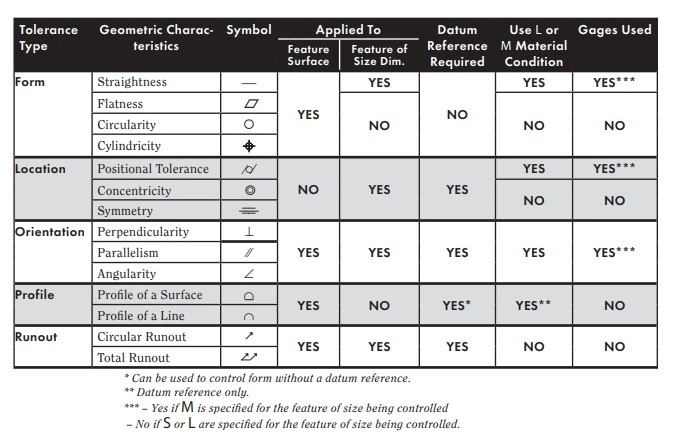
The GD&T system uses a set of symbols, rules, and definitions to specify the allowable variation in form, size, orientation, and location of features on a part. It provides a more comprehensive and precise way of expressing design requirements compared to traditional linear dimensioning.
The basic components of GD&T include:
Geometric Features: These are specific shapes or elements on a part, such as lines, circles, cylinders, and surfaces.
Tolerances: GD&T defines allowable variations or tolerances for each geometric feature. Tolerances can be expressed in various ways, such as ±0.1 mm, or using more specific symbols and modifiers.
Datum: A datum is a theoretically perfect feature used as a reference for establishing the location and orientation of other features.
Symbolic Language: GD&T uses specific symbols, letters, and numbers to represent geometric control information. Some common symbols include position, concentricity, flatness, parallelism, perpendicularity, etc.
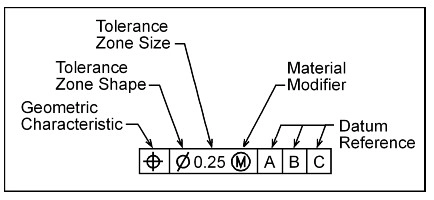
Let’s take a sample to learn it better –
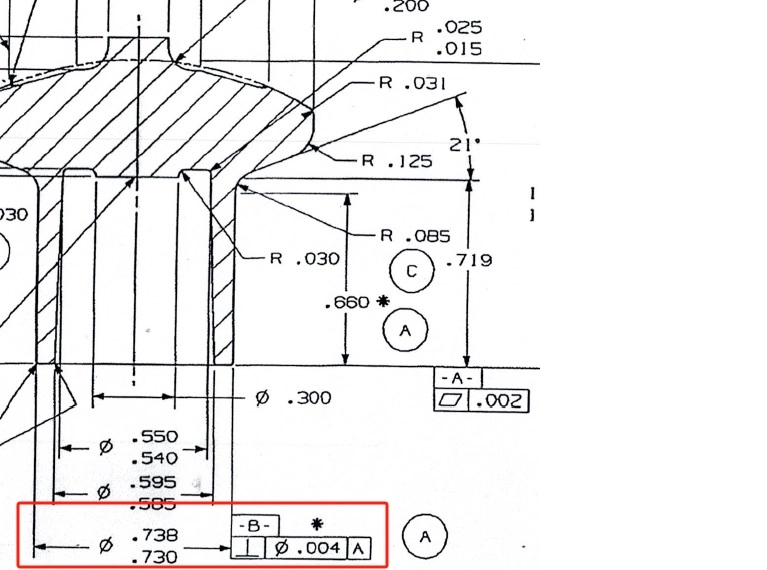
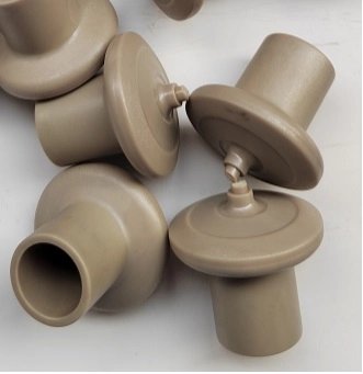
The dimension Ø .730/.738 with a perpendicularity tolerance of .004 means that this cylindrical feature must remain within 0.004 inches of perfect perpendicularity relative to the specified datum (A).
Understanding Perpendicularity Tolerance:
Perpendicularity controls how much a feature (such as a cylindrical surface or hole) can deviate from being perfectly 90° relative to a reference surface (datum A).
The Ø symbol in the perpendicularity tolerance (Ø .004 A) means that this is a cylindrical tolerance zone with a diameter of 0.004 inches.
This means that the axis of the measured feature (Ø .730/.738) must stay within an imaginary cylinder of .004 inches diameter, perfectly aligned perpendicular to datum A.
How to Measure Perpendicularity:
Setup:
Secure the part on a surface plate with datum A firmly referenced.
Ensure the datum surface is flat and stable, using a precision fixture if necessary.
Using a CMM (Coordinate Measuring Machine):
Measure several points along the cylindrical feature (Ø .730/.738).
The CMM will calculate the axis of the measured cylinder and compare it to a theoretical perfect perpendicular axis.
If the axis deviates more than .004 inches within the tolerance zone, the part is out of spec.
Using a Dial Indicator and Height Gauge:
Place a dial indicator against the cylindrical surface.
Rotate the part slowly while keeping the indicator fixed.
Any wobble or deviation beyond .004 inches indicates an out-of-tolerance condition.
Using a V-Block and Indicator:
Place the cylindrical feature in a V-block, ensuring datum A is flat on the surface plate.
Use a height gauge with an indicator to check for perpendicular deviation.
Pass/Fail Criteria:
If the cylinder’s axis remains within the .004-inch cylindrical tolerance zone, it passes.
If the deviation exceeds .004 inches, the part fails.