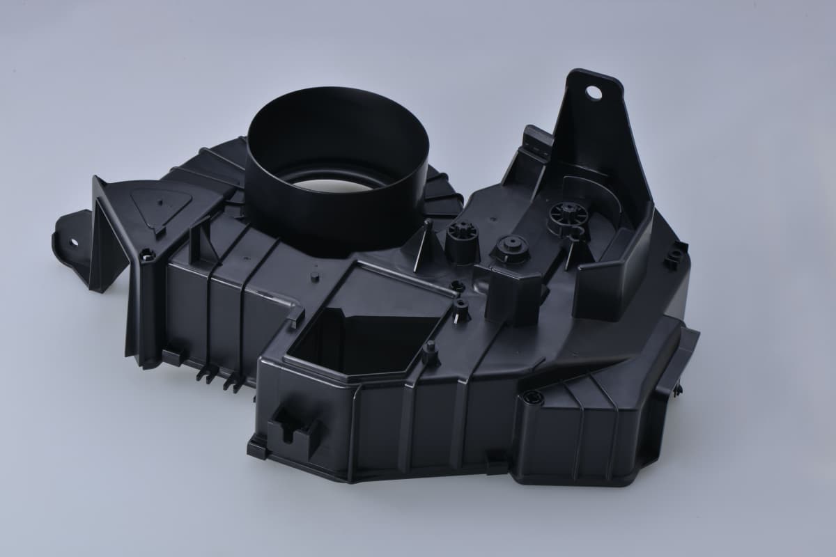

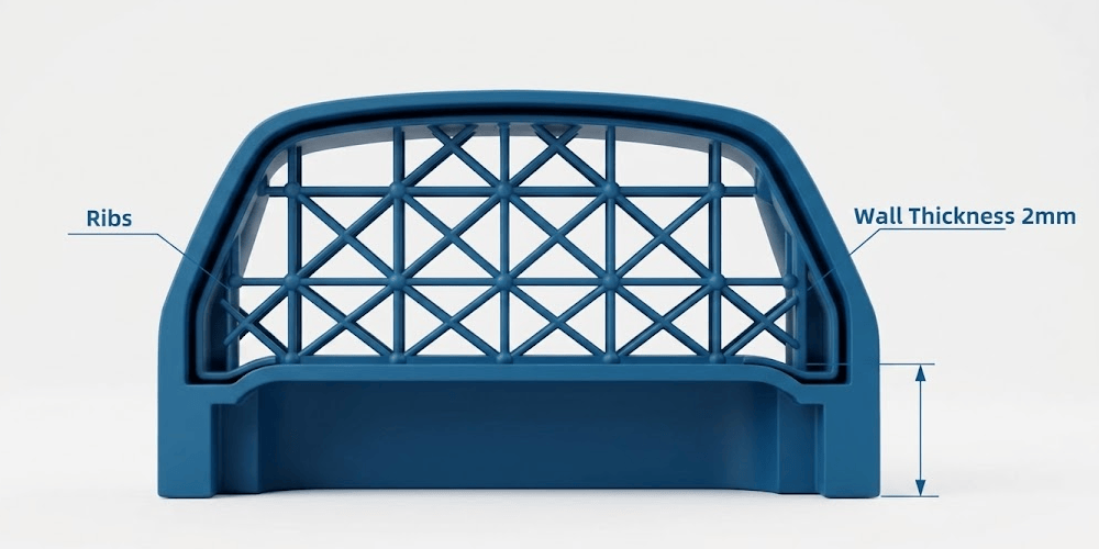
In plastic part engineering, increasing nominal wall thickness to gain structural strength leads to longer cycle times, higher material costs, and severe cosmetic sink marks. The standard approach in professional injection molding design is to use structural ribs for bending stiffness and cylindrical bosses for mechanical fastening. Designing these features requires strict control over wall thickness ratios, draft angles, root radii, and coring techniques.
This guide breaks down the dimensional rules for designing ribs and bosses, details defect prevention strategies, and outlines how early Design for Manufacturability (DFM) reviews bridge the gap between CAD models and high-yield production.
Table of Contents
- Engineering Guidelines for Injection Molded Ribs
- Best Practices for Designing Molded Screw Bosses
- Troubleshooting Rib and Boss Molding Defects
- Why Early DFM Review Matters for OEM Sourcing
- Key Takeaways
- Frequently Asked Questions
1. Engineering Guidelines for Injection Molded Ribs
Ribs provide rigidity along the load path of a plastic component without adding excessive mass. However, improper rib dimensions create localized thermal masses at the junction where the rib meets the nominal wall, causing differential shrinkage.
Dimensional Rules: Thickness, Height, and Spacing
To avoid sink marks on the Class-A cosmetic surface opposite a rib, the rib base thickness must remain a fraction of the nominal wall thickness:
- Base Thickness (T_rib): For standard amorphous resins (such as ABS or PC), design the rib base thickness between 40% and 60% of the nominal wall thickness (T_wall). For semi-crystalline materials with higher volumetric shrinkage (such as PP, PE, or PA), keep the ratio between 30% and 40%.
- Maximum Height (H_rib): Rib height should generally not exceed 2.5 to 3 times the nominal wall thickness. Taller ribs become difficult to fill, complicate mold venting, and increase ejection force requirements.
- Rib Spacing (S_rib): Maintain a minimum distance of 2 times the nominal wall thickness between parallel ribs. Tight spacing creates thin steel blades in the mold cavity that run hot, degrade cooling efficiency, and increase tooling wear.
Recommended Design Parameters
| Parameter | Recommended Dimension | Primary Engineering Objective |
|---|---|---|
| Rib Base Thickness (T_rib) | 0.4 to 0.6 x Nominal Wall | Prevents sink marks on reverse cosmetic faces |
| Maximum Rib Height (H_rib) | <= 3.0 x Nominal Wall | Minimizes mold filling resistance and ejection drag |
| Draft Angle (per side) | 0.5° to 1.5° | Ensures clean part release without drag marks |
| Internal Root Radius (R_root) | 0.25 to 0.4 x Nominal Wall | Eliminates notch sensitivity and stress concentration |
| Spacing Between Ribs (S_rib) | >= 2.0 x Nominal Wall | Maintains sufficient mold steel width for uniform cooling |
Draft Angles, Radii, and Orientation Strategies
Every vertical feature in an injection mold requires a draft angle. For structural ribs, specify a minimum of 0.5° of draft per side, increasing to 1.0°–1.5° for deeper ribs or textured tool finishes.
Sharp internal corners create localized stress concentrations that lead to premature fatigue cracking under mechanical load. Apply a fillet radius between 25% and 40% of the nominal wall thickness at the base of the rib. Orient ribs parallel to the primary melt flow path whenever possible. Ribs perpendicular to the resin flow act as internal dams, causing flow hesitation, weld lines, and premature freezing.
When developing complex structural assemblies, validating these features using rapid prototyping for design validation helps confirm stiffness and fit before committing to production tooling.
2. Best Practices for Designing Molded Screw Bosses
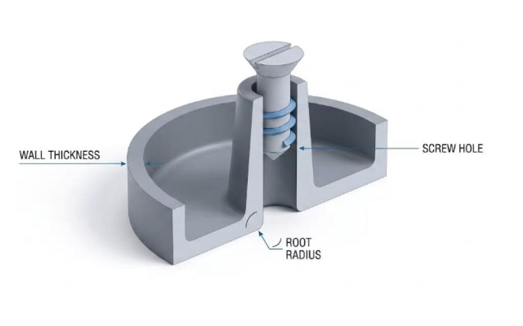
Bosses serve as mounting points, locator pins, and screw standoffs for self-tapping fasteners or heat-stake brass inserts. Because bosses are cylindrical, they are prone to developing heavy internal mass sections if designed as solid projections.
Wall Thickness, Coring Out, and Root Radii
The outer wall thickness of a boss should follow the same rules as rib base thickness: 40% to 60% of the nominal wall thickness. Designing a boss with thick walls generates a localized hot spot during cooling, resulting in deep sink marks on the cosmetic surface and internal voids within the boss itself.
- Coring to Nominal Wall: Standoff bosses must be cored out from the bottom or side to maintain uniform nominal wall thickness. The core pin should extend to the base plane of the main wall, with a small bottom radius to distribute mechanical loads.
- Hole Depth and Draft: Blind core holes should include a 0.25° to 0.5° draft angle. Ensure the core pin length does not exceed 3 times its diameter to prevent tool pin deflection (core shift) under high injection pressures.
- Root Radii: Blend the boss base into the parent wall with a generous fillet radius (0.25 to 0.5 times nominal wall) to withstand drive torque and pull-out forces.
Design Comparison: Poor vs. Recommended
POOR DESIGN (Thick Junction / Sink Risk):
In the poor design, the boss wall thickness exceeds 0.8 times the nominal wall thickness. This creates a heavy thermal mass at the junction where the boss meets the main wall, resulting in a sink mark on the opposite cosmetic surface.
RECOMMENDED DESIGN (Cored & Gusseted):
In the recommended design, the boss is cored out at the base to maintain uniform wall thickness throughout the part. External gussets are added to provide bending strength, and a generous root radius is applied at the base to distribute mechanical stress evenly.
Bosses Attached to Sidewalls vs. Standalone Bosses
Placing a boss directly against an exterior part wall creates a thick joint that traps heat and sinks. Two design solutions resolve this issue:
- Isolated Boss with Connecting Rib: Move the boss away from the sidewall by at least 1.5 to 2 times the wall thickness, then link the boss to the sidewall using a structural rib designed to standard rib-thickness rules.
- External Gusset Plates: For standalone tall bosses subjected to side loads, add 2 to 4 triangular gussets around the perimeter rather than thickening the main cylindrical wall. Gussets should follow standard rib thickness rules (40%–60% of nominal wall) and terminate below the top of the boss to ease fastener entry.
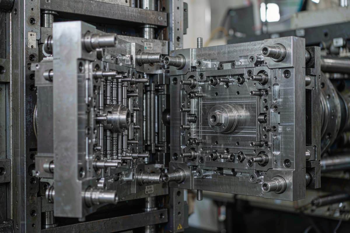
Precision execution of these tight tolerances requires high-precision plastic mold fabrication with balanced conformal cooling and hardened core pins.
3. Troubleshooting Rib and Boss Molding Defects
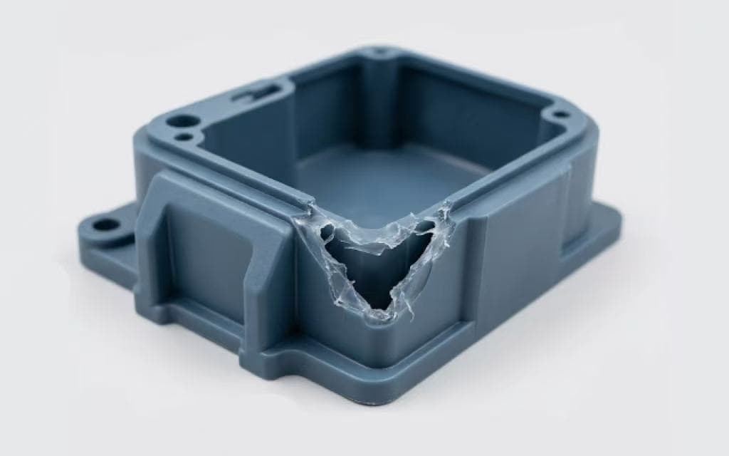
When molding structural components, improper geometry interacts directly with process parameters to create visual or structural flaws. The matrix below outlines how part design and process parameters collaborate to resolve these defects during injection molding quality control reviews.
| Defect Type | Primary Design Root Cause | Tooling & Process Countermeasure | Quality Control Focus |
|---|---|---|---|
| Sink Marks | Rib or boss base thickness exceeds 60% of nominal wall. | Increase pack/hold pressure; core out thick sections; optimize gate location. | Optical surface profilometry on cosmetic surfaces. |
| Weld Lines | Melt split around multiple bosses/ribs and cools before fusing. | Increase melt/mold temperature; relocate injection gates; add local vents. | Microscopic inspection and tensile torque testing at boss junctions. |
| Air Traps / Burns | Tall, unvented ribs trap air at the rib tip during rapid filling. | Add venting inserts or ejector pins along the rib spine. | Visual inspection for scorch marks and short-shot voids. |
| Part Warpage | Asymmetrical rib layouts causing uneven shrinkage tension. | Rebalance rib layout; calibrate differential mold temperature zones. | Coordinate Measuring Machine (CMM) dimensional verification. |
| Ejection Pin Damage | Inadequate draft angles on deep ribs causing excessive drag. | Apply polished tool surface finishes; increase draft angle to >= 1.0°. | Visual check for white stress marks or push-out witness marks. |
If your application involves both rigid structural housings and specialized dispensing mechanisms, using standardized precision components such as dual-component cartridges ensures seamless integration between molded enclosures and functional dispensing assemblies.
4. Why Early DFM Review Matters for OEM Sourcing
Optimizing CAD features for rib-to-wall ratios and draft angles is only the first step. Translating a 3D digital model into a robust, high-volume production process requires tight collaboration with an experienced China injection molding company that prioritizes engineering-driven manufacturing.
Working with an injection molding OEM manufacturer during the prototyping and tooling design phases provides several distinct advantages:
- Moldflow Simulation: Computational flow analysis identifies knit line positions, air traps, and volumetric shrinkage percentages around complex boss arrays before cutting steel.
- Tooling Life and Maintenance: Professional toolmakers specify premium mold steels (such as H13 or S136) and optimize ejection pin placement directly beneath rib intersections to prevent part distortion.
- Intellectual Property Protection: Enterprise B2B buyers require complete confidentiality. Trustworthy manufacturers operate under comprehensive non-disclosure agreements (NDAs) to safeguard proprietary CAD designs and tooling assets.
- Direct Engineering Communication: Direct, bilingual engineering support prevents design intent from being lost in translation, reducing tooling iteration cycles and accelerating time-to-market.
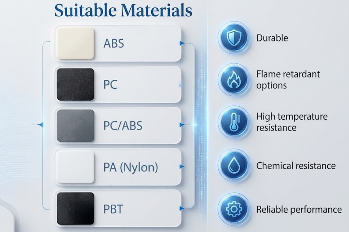
For projects with diverse polymer requirements, exploring comprehensive plastic injection molding services and specialized thermoset and thermoplastic molding solutions ensures the chosen material matches your structural, thermal, and chemical resistance requirements.
5. Key Takeaways
- The 40%–60% Golden Rule: Keep the base thickness of ribs and bosses within 40% to 60% of the nominal wall thickness to avoid cosmetic sink marks.
- Core Out Solid Bosses: Avoid solid cylindrical features; core out the base of all bosses to maintain uniform nominal wall thickness.
- Incorporate Generous Radii: Apply root radii of 25% to 40% of the wall thickness at the base of ribs and bosses to eliminate stress concentration without creating thick mass sections.
- Draft Is Non-Negotiable: Apply at least 0.5° to 1.5° of draft per side on all ribs and bosses to facilitate clean ejection and protect mold tooling.
- Engage in Upfront DFM: Submit CAD files for moldflow simulation and DFM review before finalizing tooling to eliminate expensive mold rework.
6. Frequently Asked Questions (FAQ)
What is the ideal rib thickness compared to nominal wall thickness?
In standard injection molding design, the rib base thickness should be 40% to 60% of the adjacent nominal wall thickness for amorphous plastics (such as ABS, PC, and PS). For semi-crystalline plastics with higher shrinkage rates (such as PP, PE, and PA), maintain a thinner ratio of 30% to 40% to prevent visible sink marks.
How do you prevent sink marks behind a heavy screw boss?
To prevent sink marks, core out the bottom of the boss to maintain consistent nominal wall thickness throughout the part. Additionally, isolate the boss from exterior sidewalls by at least twice the nominal wall thickness, and use thin structural ribs or external gussets to provide lateral stability.
What minimum draft angle is required for deep structural ribs?
Specify a minimum draft angle of 0.5° per side for smooth, polished tool cavities. If the rib height exceeds 25 mm or features EDM/textured surface finishes, increase the draft angle to 1.0°–1.5° per side to reduce friction and prevent ejection damage.
How does GoodTech handle confidential CAD files during the DFM process?
GoodTech safeguards intellectual property by executing strict Non-Disclosure Agreements (NDAs) before receiving 3D CAD files. All project data is managed internally by engineering teams using secure servers, ensuring complete client confidentiality from initial DFM analysis through mass production.
Ready to Optimize Your Rib and Boss Design?
Upload your 3D design to GoodTech to request a DFM review for plastic injection molding. Our engineering team will review your rib and boss geometry, evaluate moldflow feasibility, and deliver actionable design feedback under a strict Non-Disclosure Agreement.