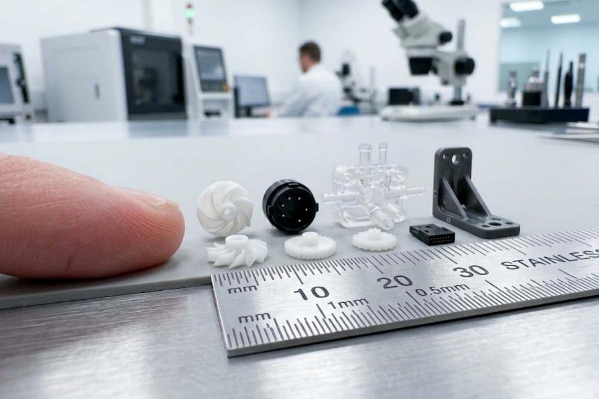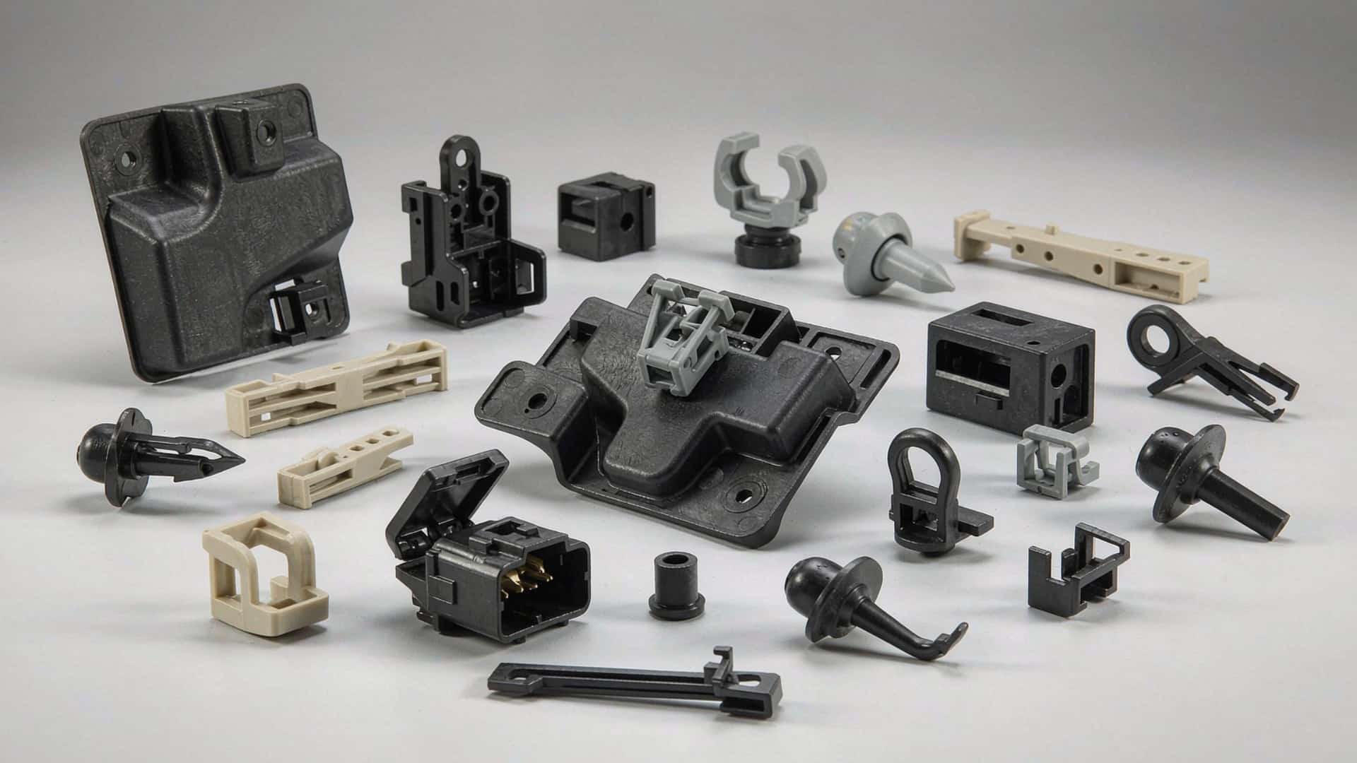

Not every small part is a micro molded part. In practice, micro injection molding is defined by three numbers: a part weight under roughly one gram, overall dimensions under roughly 10 mm, and — most importantly — functional features measured in micrometers, typically below 0.1 mm and held to tolerances in the ±0.005–0.02 mm band. Cross that line and the machine, the mold, the material and the inspection method all have to change; below it, you are paying micro molding prices for a part that a conventional press would run faster and cheaper.
Four decisions drive the outcome. First, whether your feature size genuinely crosses the micro threshold, because that determines which suppliers can even quote. Second, which resin can fill those features at all. Third, what tolerance is realistic rather than what is drawn. Fourth, whether your annual volume belongs in a mold, in a micro 3D printer, or in a machining center.
This guide works through those four decisions in order, with the design-rule differences, tolerance limits and material trade-offs that engineers are usually asked to resolve before a tool is cut.
Key Takeaways
- Three criteria define micro molding, but only the third is decisive: functional features below about 0.1 mm, or tolerances tighter than roughly ±0.02 mm.
- A small part is not automatically a micro molded part. Part weight and overall size alone do not force a change of machine.
- Four things change at micro scale: shot size and metering, melt residence time, part removal and handling, and the inspection method.
- Achievable tolerance is set by material shrinkage, mold machining accuracy, metering repeatability and demolding deformation — not by the tolerance block on the drawing.
- At feature sizes below roughly 0.2 mm, flow behaviour and additive particle size decide whether the cavity fills, which is why glass-filled grades are usually the wrong first choice.
- Conventional DFM values for wall thickness, gate size, draft and venting were written for parts you can measure with calipers and do not transfer directly.
- Micro molding wins on cost per part at volume; micro 3D printing wins on prototypes and low quantities; micro machining covers metal inserts and tooling.
What Counts as “Micro” Injection Molding
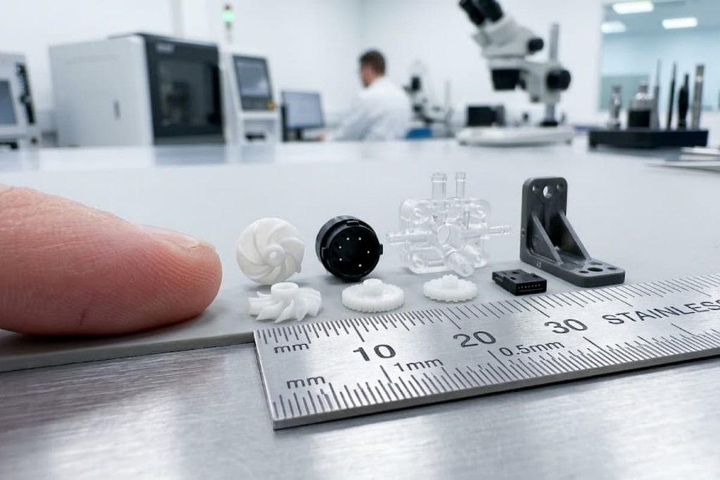
Most suppliers will call a part “micro” once it fits between your fingers. A process engineer calls it micro when the shot size — not the part size — forces a change of machine. The difference matters commercially, because it decides whether your part is quoted on a standard press or routed to equipment built around small-shot metering.
Three criteria are used to separate the two, and they do not have to be met simultaneously:
| Criterion | Typical threshold | Decisive? |
|---|---|---|
| Part weight | Under about 1 g | No — light parts are still moulded conventionally |
| Overall part size | Under about 10 mm in the largest dimension | No |
| Functional feature size | Under about 0.1 mm | Yes |
| Tolerance on functional features | Roughly ±0.005–0.02 mm | Yes |
The third and fourth lines are the ones that change the process. A 12 mm housing with 0.8 mm walls, generous radii and no micrometre-level features runs on a conventional machine with a standard mold. Calling it a micro part does not improve it; it only raises the quote and narrows the supplier list.
The same logic runs in the other direction. A part of only 4 mm that carries a 0.15 mm bore with a ±0.05 mm tolerance is still a conventional molding job. The feature is small, but the tolerance and the flow path stay within what an ordinary tool and an ordinary press can repeat. Feature geometry and tolerance travel together; part size alone tells you very little.
If you are unsure which side of the line your design sits on, the fastest answer is to compare the functional feature and its tolerance against the table above, then confirm with the supplier. That single check removes most of the mismatched enquiries that reach a micro molding department.
Why Micro Molding Is a Different Process, Not Just a Smaller One
Scaling a part down does not scale the process down with it. Four things stop behaving the way conventional molding guides assume they will.
Shot size and metering
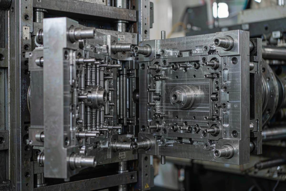
The shot is the first constraint. A general-purpose reciprocating screw delivers far more material per stroke than a micro part needs, and the barrel volume does not shrink because the part did. Micro molding machines address this with a much smaller screw diameter than general-purpose units use, or with a separate small-volume metering unit that injects through a plunger. A supplier cannot fit a smaller mold to an existing press and call the result micro molding — either the machine is configured for small shots or it is not, and this is among the first questions worth asking.
Melt residence time
Residence time is the hidden cost of a small shot. If the barrel holds a fixed melt volume and the shot consumes a fraction of it, every pellet spends longer at temperature. Thermosensitive resins — polycarbonate, acetal and several medical grades — degrade over that exposure, and the failure shows up as discoloration, splay or reduced mechanical performance rather than as an obvious short shot. Barrel sizing, shot scheduling and purge discipline are how molders manage it; depending on the material and the machine configuration, the safe window can be narrow, and the exact figure should be confirmed with the molder.
Demolding and part handling
Ejection is where micro parts are physically lost. An ejector pin witness mark that passes on a 100 mm housing is a defect on a 0.4 mm feature, so micro molds use air ejection, full-plate ejection or a controlled stripping action designed so that nothing touches a functional surface. Handling creates the same problem: parts weighed in milligrams are easily damaged, attracted to surfaces by static, or simply lost, which is why automated take-out with vision sorting is the normal arrangement rather than an option.
Inspection and metrology
Micro parts cannot be measured the way macro parts are. A touch-trigger CMM probe is frequently larger than the feature it is meant to measure, and its contact force can deform a thin wall before it registers a point — which is why industrial computed tomography and vision metrology move from the quality report into the design conversation. Inspection capability therefore becomes a design constraint: a critical feature that cannot be measured repeatably carries a tolerance that cannot be verified. Our plastic injection molding capabilities page covers the standard process side; the metrology question is specific to micro scale and should be settled before tooling starts.
Tolerances for Micro Molded Parts: What Is Actually Achievable
Achievable tolerance on a micro molded feature is set by four variables — material shrinkage behaviour, mold machining accuracy, metering repeatability and demolding deformation — not by the tolerance block on your drawing. If you need the general framework for molded part tolerances first, our guide to achievable injection molding tolerances covers the standard grades; the ranges below describe what changes once the feature itself is measured in micrometres.
| Feature class | Indicative band for micro molded parts | What sets the limit |
|---|---|---|
| Overall part dimensions | ±0.02–0.10 mm | Shrinkage behaviour, part size, mold construction |
| Mating and assembly features | ±0.01–0.03 mm | Shrinkage anisotropy, gate location, tool wear |
| Functional micro features (below about 0.5 mm) | ±0.005–0.02 mm | Metering repeatability, mold machining accuracy, demolding |
| Feature-to-feature position | ±0.005–0.02 mm | Tool accuracy and thermal stability during the run |
These bands are indicative ranges reported across micro molding practice, not approval limits, and they are not a substitute for a part-specific review. The value for a specific feature depends on the resin, the geometry and the mold construction, and the exact specification should be confirmed with the supplier against the drawing.
The four variables behind the number
Material shrinkage is the first. Semi-crystalline resins shrink more than amorphous ones, and shrinkage is not uniform in every direction, so a feature running along the flow direction and a feature running across it will not move by the same amount.
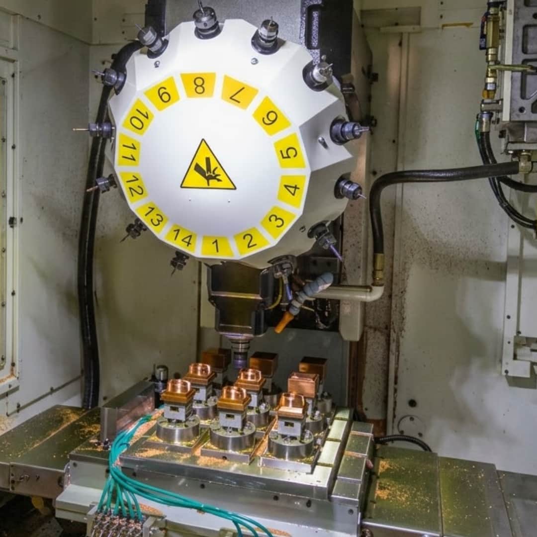
Mold machining accuracy is the second, and it sets a hard ceiling. No molding process can hold a tolerance tighter than the cavity it fills. Our tooling group publishes cavity dimensional capability to ±0.003 mm on the CNC machining side, which is the kind of margin a micro feature needs — confirm the achievable value for your specific geometry rather than assuming the published figure transfers directly.
Metering repeatability is the third. Shot-to-shot variation in the injected volume translates directly into dimensional variation in the part. A machine that repeats its shot volume well is worth more on a micro job than one with a larger clamping force.
Demolding deformation is the fourth and the most underestimated. Thin micro features have very little stiffness, so the force that removes the part can also bend it. Tolerances that were met at room temperature on a free-standing part may not survive ejection, and this is why the measurement plan and the ejection concept have to be agreed together.
Material Selection for Micro Parts
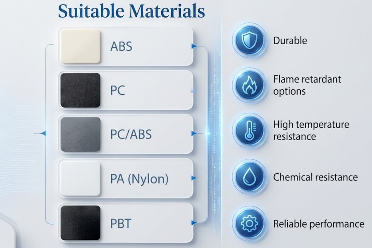
At feature sizes below roughly 0.2 mm, material selection is driven by flow behaviour rather than by the mechanical values on the data sheet. Melt viscosity and additive particle size decide whether the cavity fills at all; tensile strength and heat deflection temperature only matter after that question is answered.
| Material family | Why it is selected for micro parts | What to plan for |
|---|---|---|
| PEEK | High temperature and chemical resistance for medical and industrial micro parts | High melt temperature and viscosity — needs adequate injection pressure and short flow paths |
| PSU / PES | Dimensional stability at temperature, with transparent options | Hygroscopic; drying discipline directly affects part quality |
| PC | Toughness and clarity in micro housings and optical parts | Sensitive to residence time — degradation and yellowing risk |
| POM (acetal) | Low friction and moulding stability for micro gears and sliding parts | Low thermal stability; long residence times are a risk |
| COC / COP | Low water absorption with good optical and electrical behaviour | Narrow processing window; melt temperature needs close control |
| LSR (liquid silicone rubber) | Elasticity and biocompatibility where thermoplastics cannot deliver | A separate process with its own dosing equipment, not a drop-in substitution |
| Bioresorbable grades | Resorbable implants and single-use devices | Very sensitive to moisture and thermal history |
Why glass-filled grades are usually the wrong first choice
Reinforcement helps a large structural part and works against a small one. Glass fibres in a micrometre-scale channel orient along the flow path, and where the channel narrows to a gate the fibre length becomes comparable to the passage itself. The result is uneven fill, a sintered-looking surface, and in the worst case a blocked gate.
For most micro parts the practical starting point is an unfilled or lightly filled grade, with reinforcement considered only after a filled grade has been shown to fill and release reliably. Glass content that looks modest on a data sheet can still be too high for a 0.2 mm feature.
When to switch to liquid silicone rubber
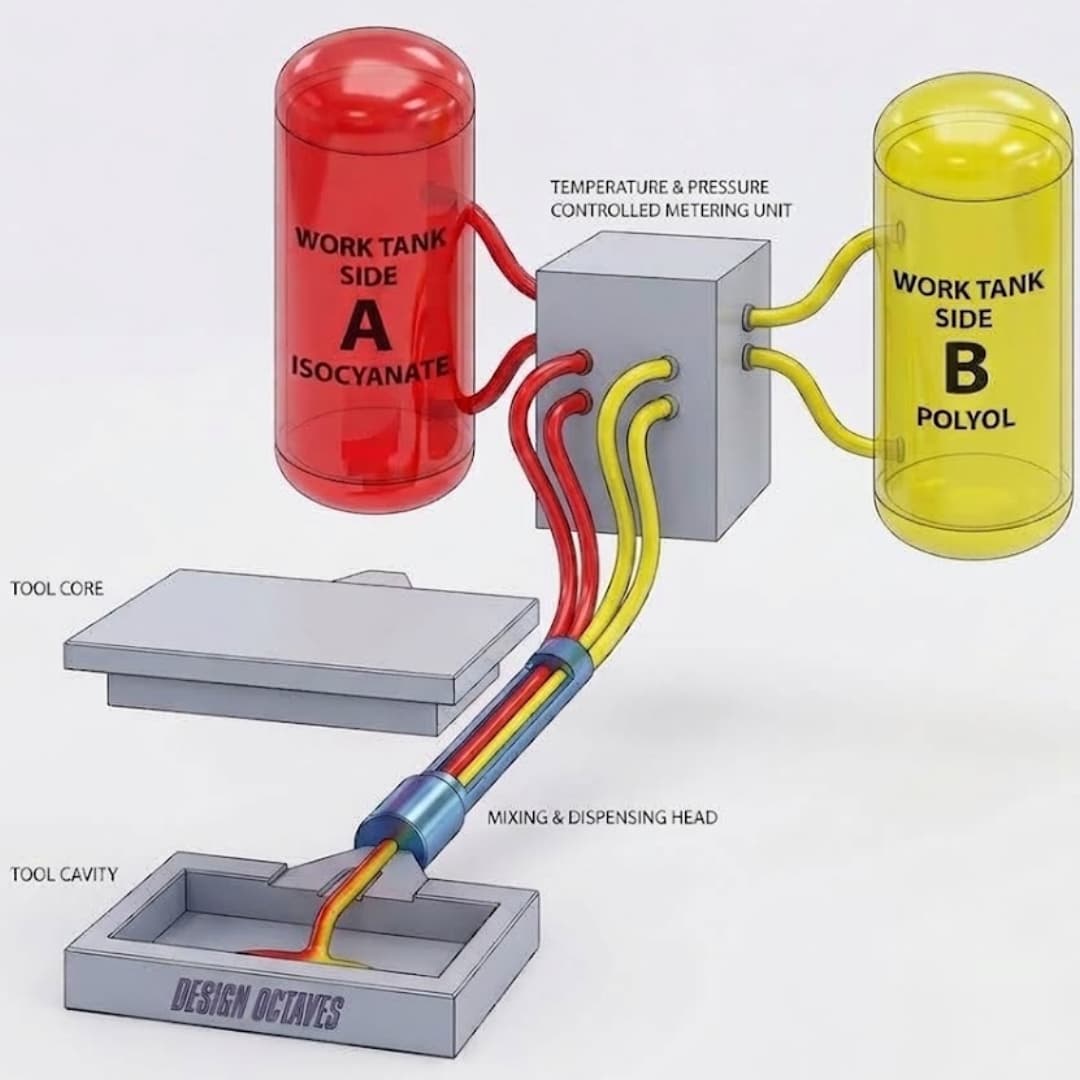
LSR is not a material substitution — it is a different manufacturing route. It arrives as a two-component liquid, is dosed by volume rather than melted from pellets, and cures in the mold. That makes it the right answer when the part must flex, when it must survive repeated sterilisation, or when a soft-touch seal has to be formed at micro scale.
For medical applications where material compliance drives the decision, our notes on medical grade material selection set out how the grade requirements are normally established, including the point at which the compliance route should be confirmed with the supplier rather than assumed from a data sheet.
Design Rules for Micro Molded Parts (DFM)
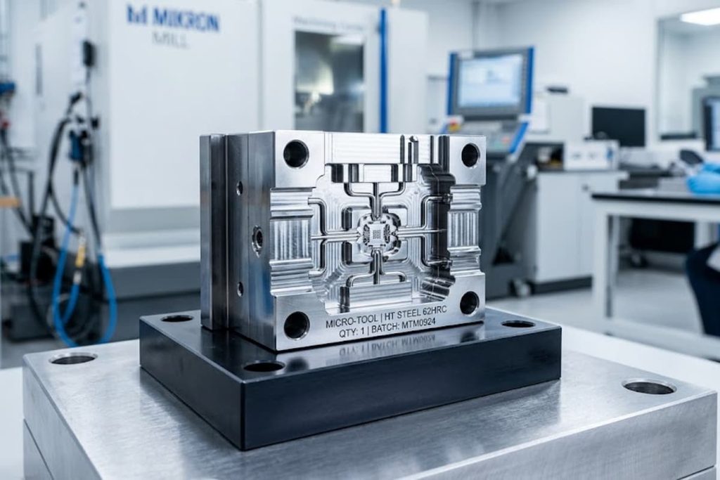
Standard DFM rules — wall thickness above 0.5 mm, gate diameter above 0.8 mm, one degree of draft — were written for parts you can measure with calipers. Micro parts break all three, and the rewritten values are what separate a supplier that specialises in micro molding from one that simply owns a small press.
| Design element | Conventional DFM convention | What changes at micro scale | Why it changes |
|---|---|---|---|
| Minimum wall thickness | 0.5–1.0 mm | Set by the flow-length-to-thickness ratio and melt viscosity; can fall below the conventional minimum | Viscous effects dominate once the channel is measured in micrometres |
| Gate size | 0.8 mm and above | Can be reduced to a fraction of a millimetre where the tool can be machined to that accuracy | The gate is the restriction that sets fill pressure |
| Draft angle | 1–2° | Often needs a larger relative draft, or a different ejection concept | Friction and adhesion effects grow as the feature shrinks |
| Corner radii | 0.5 mm and above | Limited by the smallest cutter or electrode the tool shop can produce | Mold making, not molding, sets the geometric limit |
| Venting | Standard vent channels | Requires micron-scale vents or vacuum assistance | Gas cannot escape a micro cavity through conventional vents |
| Flow length ratio | Commonly 100:1–150:1 | Narrows considerably and has to be calculated per part | Pressure loss in micro channels is rapid |
Treat the “what changes” column as a direction rather than a table of replacement numbers. The correct values for a given part depend on the resin, the wall section and the mold construction, and they should be settled in a DFM review against the actual drawing. The conventional baseline for those rules is covered in our injection molding design guide; what follows is the set of mistakes that most often turn a workable micro design into an unquotable one.
Four design mistakes that make a micro part unquotable
Applying a tight tolerance to the wrong dimension. A tight overall dimension tolerance is expensive to hold and usually irrelevant to function. Put the tight band on the feature that has to mate or perform, and relax everything else. This single change often moves a part back into a workable tolerance class.
Placing critical features far from the gate. In a micro cavity the pressure needed to fill rises quickly with flow length. A functional feature at the end of a long thin path will short-shot before the gate is full, and the fix is a gate position change, not a higher injection pressure.
Designing without a handling surface. Micro parts are removed, sorted and packed automatically. If the design offers nothing for a gripper or a vacuum cup to hold, the part will be picked up by a functional face and damaged. A small moulded tab or a flat area costs nothing and prevents a recurring defect.
Assuming conventional side actions can simply be scaled. A side core or an unscrewing mechanism that works at 20 mm does not shrink to 2 mm. Where a micro part needs a side feature, it is usually cheaper to redesign the geometry so the feature can be formed on the parting line than to build micrometre-scale side action.
Where a micro part has to combine polymer with a metal or ceramic element, the tooling questions shift to insert location and retention — covered in our insert molding guide.
Micro Insert Molding & Micro Overmolding
Insert molding and overmolding at micro scale are limited less by the molding process than by the insert. Positioning a 0.2 mm pin or a fine contact within ±0.01 mm requires tooling features with no equivalent at conventional size, and the insert itself has to survive the injection pressure without moving.
Three insert types account for most micro work: metal pins and contacts that provide conductivity or mechanical anchoring, ceramic elements that carry optical or dielectric function, and light guides or fibres that must be held in precise registration with a lens or a sensor. In each case the design question is the same — whether forming the polymer over the insert reduces the tolerance stack enough to justify the tooling.
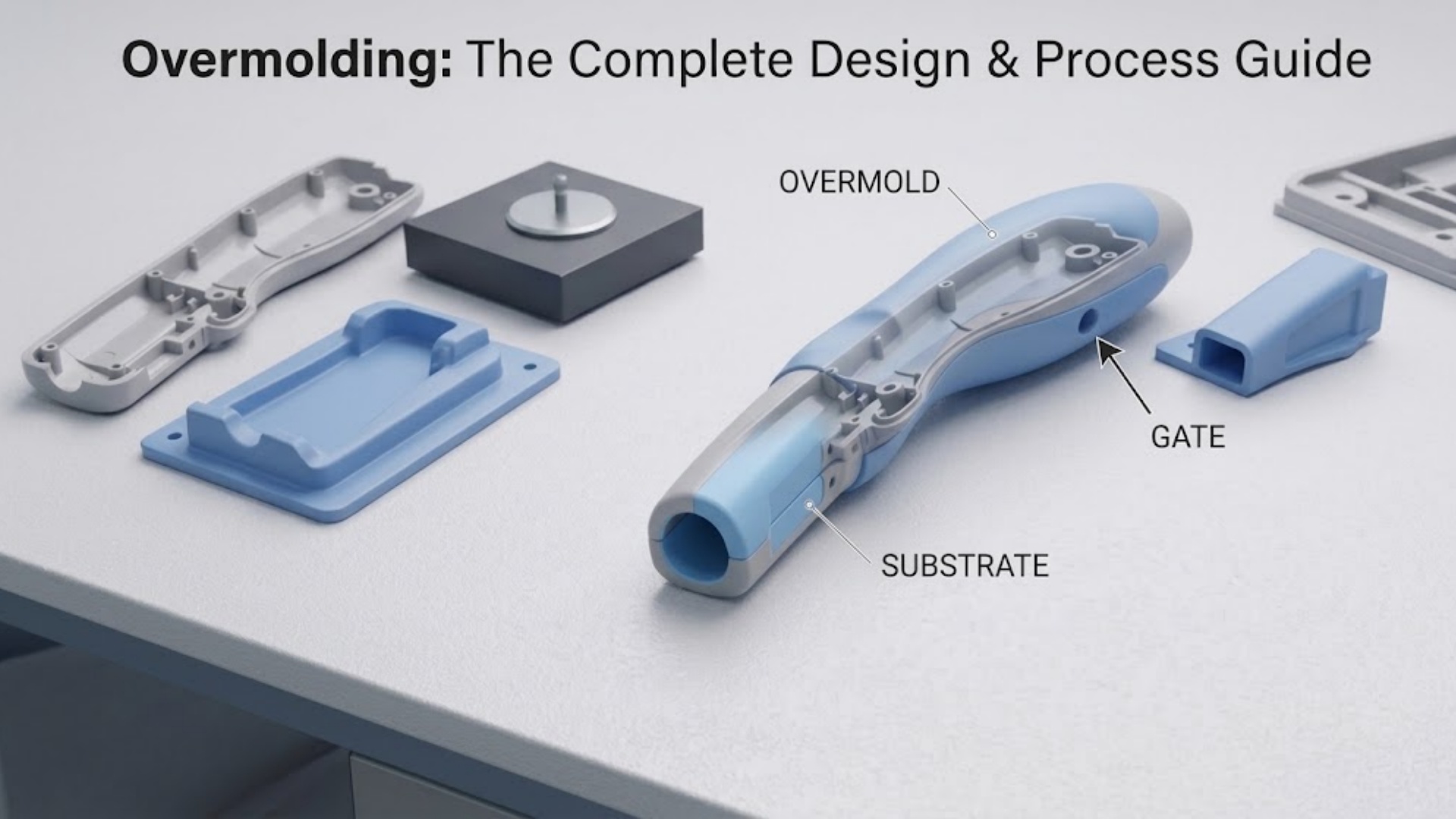
It is worth combining the two operations when the assembly tolerance chain is the dominant risk, and worth separating them when the insert can be placed accurately afterwards with a standard press or adhesive. Overmolding at micro scale is usually chosen for sealing and for soft-touch or living-hinge behaviour, and the design constraints are set out in our overmolding design guidelines. The boundary between the two approaches is a tolerance question, not a preference.
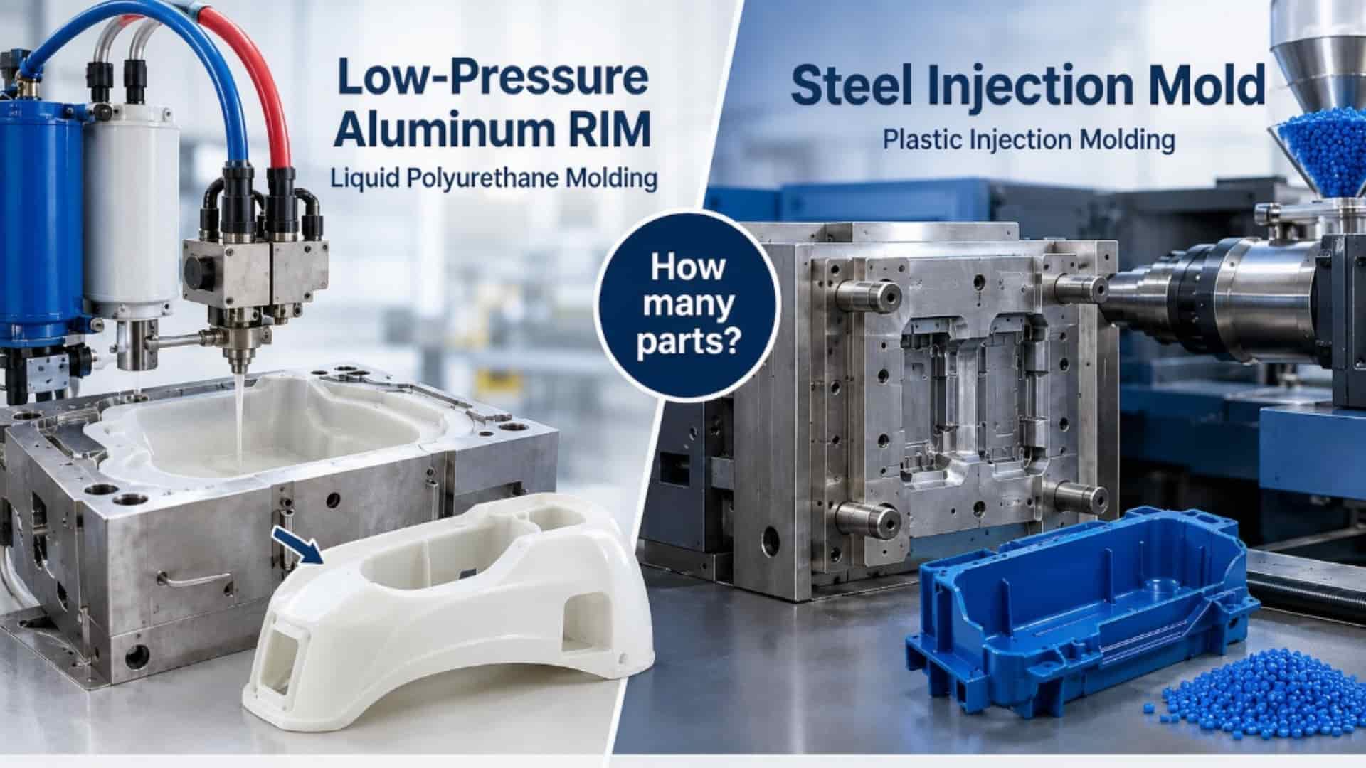
Micro Molding vs Micro 3D Printing vs Micro Machining
For a prototype, micro 3D printing wins. For anything past a few thousand units a year, micro molding usually wins on cost per part — but only if the tolerance and material requirements are compatible with it.
| Criterion | Micro injection molding | Micro 3D printing | Micro machining |
|---|---|---|---|
| Geometry freedom | Limited by draft, ejection and gate access | Highest — internal channels and lattice structures are possible | Limited to what a cutting tool can reach |
| Material range | Engineering thermoplastics and LSR | Printable resins, with limited metal and ceramic options | Metals, ceramics and plastics |
| Cost per part as volume rises | Falls sharply | Broadly flat, so it loses ground at volume | Falls, but more slowly than molding |
| Volume fit | Production quantities | Prototypes, design validation, bridge quantities | Low to medium volumes and hard-material parts |
| Surface finish | Controlled by the mold, repeatable across the run | Layer-dependent | Controlled by the tool path |
| Typical use | Series production of micro parts | Concept and fit validation | Mold inserts, small metal components, prototypes |
A four-question decision framework
Work through these in order; the first “no” usually settles the route.
- Does the part have functional features below about 0.1 mm, or tolerances tighter than roughly ±0.02 mm? If not, a conventional mold is likely the cheaper answer, and the micro question does not arise.
- What is the annual volume? Prototypes and a few hundred units favour 3D printing. Once the part is going into a product, the tooling cost is amortised and molding takes over.
- Which material is genuinely required? If only a printable resin meets the specification, that decides it. If PEEK, LSR or another engineering grade is required, molding is the route.
- Is the geometry moldable? Undercuts, internal channels and zero-draft features that cannot be ejected point to printing or machining, or to a redesign.
Quality & Documentation for Micro Parts
Micro parts cannot be inspected the way macro parts are, so the inspection plan is part of the design work rather than a document produced afterwards. Three elements need to be agreed before the tool is cut: the datum scheme and measurement method for each critical feature, the list of features that are actually critical, and the capability target the supplier is expected to demonstrate over the run.
Industrial computed tomography and vision metrology are the usual answers for internal geometry and for features too small for contact probing, and contact measurement still has a role where the feature and the material can take it. The exact method and the sample size should be confirmed with the supplier against your drawing — a measurement method agreed after tooling is a rework cost, not a quality improvement.
Where parts go into regulated products, documentation requirements such as material traceability, cleanroom conditions and inspection records sit alongside the molding specification. Those requirements are separate from the process question, and the process behaviour described here applies either way.
FAQ
How small can an injection molded part be?
Micro molded parts are commonly produced below 1 g in weight and under about 10 mm in overall size, with functional features below 0.1 mm. The practical limit is usually set by inspection capability rather than by the molding process itself: if a feature cannot be measured repeatably, it cannot be verified, and the achievable limit for that part effectively sits where the metrology does.
What tolerance can micro injection molding hold?
Functional micro features are commonly specified between ±0.005 mm and ±0.02 mm, with overall dimensions typically between ±0.02 mm and ±0.10 mm. The exact value depends on the material, the feature geometry, the mold construction and the metering repeatability of the machine, and it should be confirmed with the supplier against the specific drawing.
Which materials work best for micro molding?
Flow behaviour decides the shortlist. PEEK and PSU cover high-temperature and chemical-resistance applications, PC and COC/COP suit optical and housing parts, POM is common for micro gears, and LSR is used where elasticity or repeated sterilisation is required. Unfilled or lightly filled grades are generally the starting point, because glass fibres can block micrometre-scale gates.
Is micro molding more expensive per part than standard molding?
Tooling cost is higher because mold making must hold micrometre-scale accuracy and the equipment is specialised. Cost per part then falls steeply with volume, so at production quantities the difference narrows considerably. The comparison that matters is against the alternative route — 3D printing or machining — at your actual annual volume, not against a conventional mold at a volume you do not have.
When should I choose micro 3D printing instead of micro molding?
Choose micro 3D printing for prototypes, design validation and bridge quantities, and whenever the geometry cannot be ejected from a mold. Choose micro molding once the part enters series production and the required resin is a mouldable engineering grade. Where the two overlap, the decision is normally made on annual volume and on whether the material is printable.
Conclusion
The decision chain runs in one direction. Confirm that functional features are actually at micrometre scale, because that single check decides whether a micro molding route is needed at all. Choose a material that can fill those features rather than one that simply meets a data sheet target. Agree the tolerance on the features that matter, and check that the metrology exists to verify them. Only then compare micro molding against micro printing and micro machining at your real annual volume.
Parts that cross the micro threshold are quoted and built differently from the moment the design is reviewed, and the earlier those four questions are settled, the fewer changes are needed once a tool exists.
If you are evaluating a micro molded part, send us the drawing and the intended annual volume. We will return a DFM review covering achievable tolerances, gating and metering limits, and the material options that will actually fill your features. For the service side of that review, see micro injection molding services.
Technical references
- ISO 20457:2018, “Plastics moulded parts — Tolerances and acceptance conditions.” Used as the general tolerance framework against which micro molded part tolerances are compared; its grades are not applied directly to micrometre-scale features.
- Accumold, micro injection molding technical resources. Used for the definition of micro molding by feature size and shot weight, and for the machine, tooling, handling and metrology differences described in this guide; its published capability figures are not treated as universal limits.
- ARBURG, micro injection molding machine technology information. Used for the machine-side description of small-shot metering, barrel sizing and melt residence time.
- Victrex, PEEK processing and technical data guidance. Used for the high-temperature and chemical-resistance criteria in the material selection section.
- Dow, SILASTIC liquid silicone rubber processing guidance. Used for the liquid silicone rubber section, including the point that LSR is a separate dosing and curing process rather than a material substitution.
Reference entries list the sources that informed the general process and material descriptions in this article. They are not product approvals, and none of the ranges reported in them should be treated as an approval limit for a specific part.