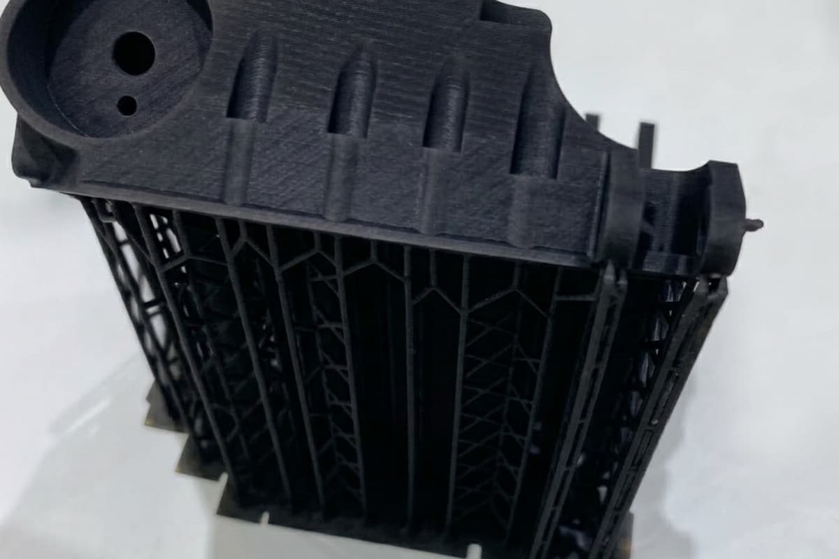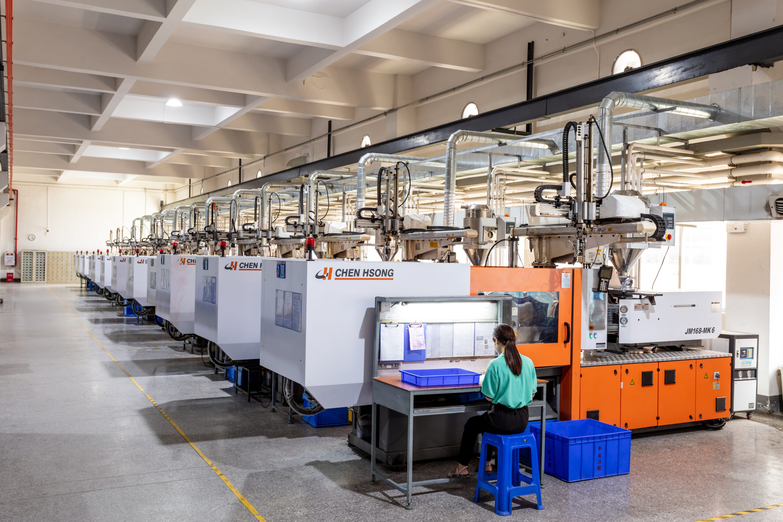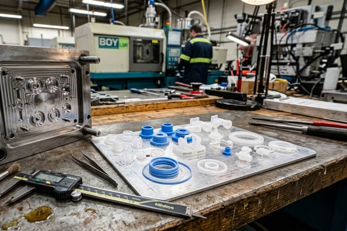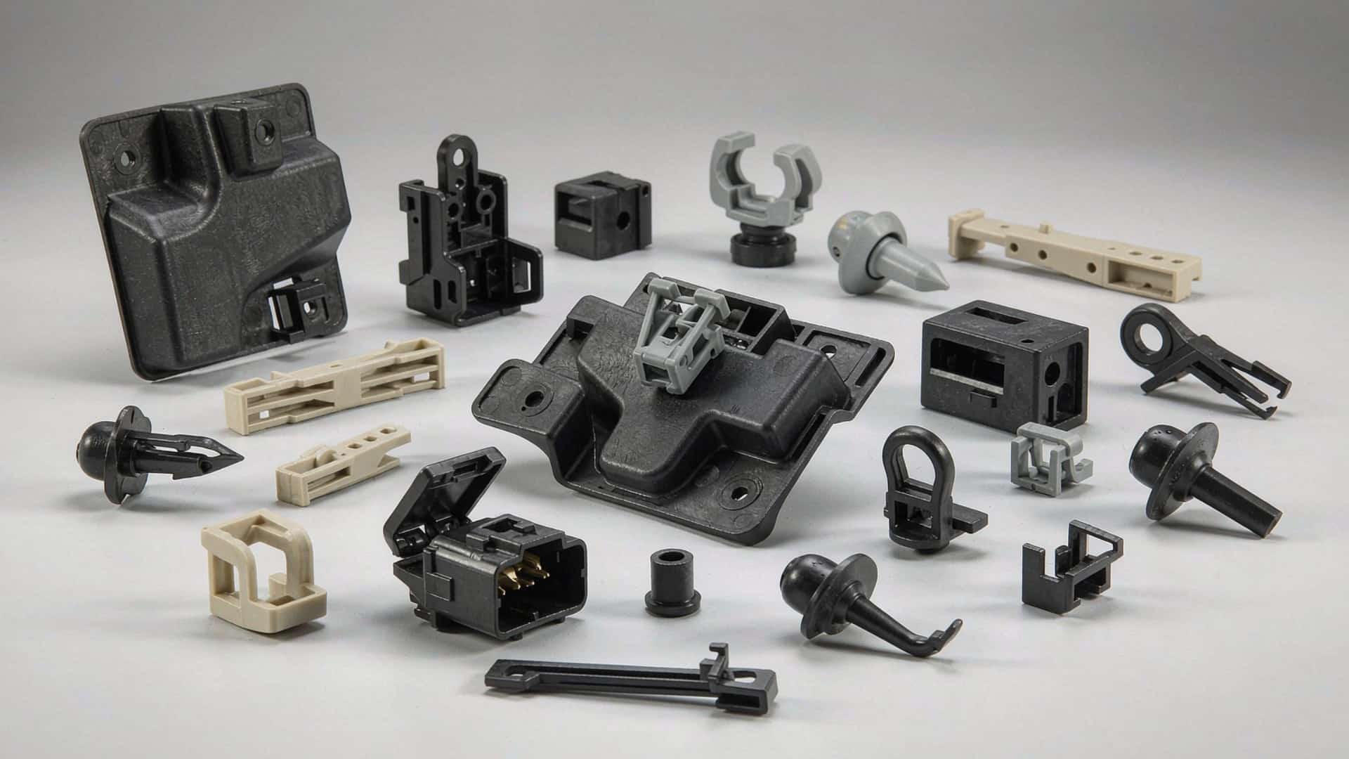

Electronics housing injection molding turns resin into the rigid shell that protects a device’s internals. The practical answer for engineers: specify the material by environment, hold a material-appropriate wall thickness, follow the 60% rib rule and boss proportions, give enough draft for the finish, and tighten tolerances only on assembly-critical features. This reference collects those numbers and rules in one place so a housing drawing can be released with confidence.
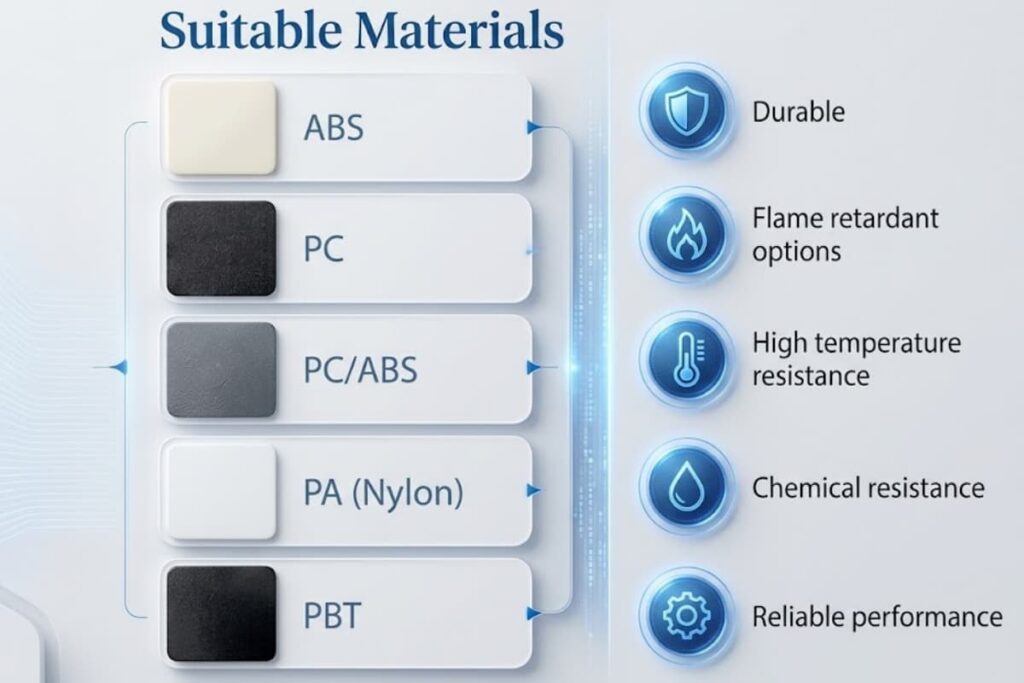
Material Shortlist for Electronics Housings
The shortlist below covers the resins most often used for consumer and industrial electronics shells. Exact grades, flame-retardant ratings, and filler content should be confirmed with the molder against your certification needs.
| Material | Strength | Heat | Appearance | Typical housing use |
|---|---|---|---|---|
| ABS | Moderate | Low–moderate | Good, glossy | Indoor shells, brackets |
| PC | High | High | Clear or glossy | Rugged, transparent parts |
| PC/ABS | Good | Good | Very good | Phone, router, remote shells |
| PA (Nylon) | High | Good | Matte | Structural, chemical-exposed |
| PBT | Moderate | Good | Matte | Connectors, bases |
For selection logic, see the engineering plastics guide.
Wall Thickness by Material (Quick Reference)
Nominal wall should suit both the material’s flow and the part’s stiffness. The ranges below are typical starting points; final value depends on part size, fill length, and press capability.
| Material | Typical nominal wall (mm) | Note |
|---|---|---|
| ABS | 1.5 – 2.5 | Easy flow; lower end for small parts |
| PC | 1.5 – 3.0 | Higher viscosity; watch flow marks |
| PC/ABS | 1.5 – 2.5 | Most consumer shells sit here |
| PA | 1.5 – 3.0 | Moisture affects final dimension |
| PBT | 1.5 – 3.0 | Stable, good for thin sections |
Keep transitions gradual and avoid thick islands. The wall-thickness reference explains why uniform walls reduce sink and warpage.
The 60% Rib Rule and Boss Design
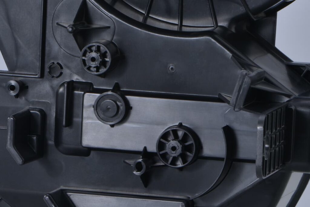
Ribs add stiffness without thickening the wall, but a rib that is too thick sinks on the opposite face.
- Rib thickness ≈ 60% of nominal wall — the widely used rule that balances stiffness against sink.
- Rib height is typically up to 3× the nominal wall before the rib needs its own draft and fillet.
- Boss outside diameter ≈ 2× the screw core diameter, with wall thickness around 60% and a fillet at the base.
- Tie bosses to a wall with a rib so they are not isolated masses that sink or warp.
Apply these in the ribs and bosses design guide.
Draft Angles and Demolding for Housings
Every vertical face needs draft so the part releases cleanly. Texture and depth increase the requirement.
| Surface | Typical draft | Note |
|---|---|---|
| Polished / glossy | 0.5° – 1° | Minimum; verify with molder |
| Light texture (SPI B) | 1° – 1.5° | Texture raises release friction |
| Deep texture (SPI C/D) | 2° – 3°+ | Confirm against texture spec |
See the minimum draft angle guide for edge cases.
Tolerances You Should Actually Specify
Specify tightly only where function demands. The features that usually earn a tight callout:
- PCB mounting boss inner diameter and standoff height
- Snap-fit engagement length and hook angle
- Connector window position and size
- Sealing interface where parting-line flash matters
Everything else can run to standard commercial tolerance. The tolerances guide and the tolerances design guide show achievable ranges.
Common Housing Defects and How Design Prevents Them
| Defect | Design root cause | Prevention |
|---|---|---|
| Sink mark | Thick section, oversized rib/boss | Uniform wall, 60% rib rule, gate placement |
| Warpage | Uneven wall, fiber orientation | Symmetric wall, balanced fill |
| Flow mark | Low temp, long flow, glossy PC | Process + gate review |
| Short shot | Thin section, remote fill | Wall/thickness and gate strategy |
Design-level fixes are detailed in the defects prevention guide and the shrink marks guide.
DFM Review Checklist Before Tooling
Before releasing the housing for tooling:
- Wall thickness uniform and within material range
- Ribs at ~60% wall; bosses tied to walls
- Draft added to every vertical face per finish
- Tight tolerances only on assembly-critical features
- Gate and ejector locations reviewed for cosmetics
- Sealing method decided if IP rating is required
The DFM design guide expands each item.
FAQ
What is the recommended wall thickness for ABS and PC electronics housings?
A nominal wall around 1.5–2.5 mm is typical for both, adjusted for part size and flow length. Confirm the exact value with your molder.
How much draft does a textured enclosure need?
Light textures often need about 1–1.5°, deeper textures 2–3° or more. Match the draft to the SPI texture spec.
How do I prevent warpage in an electronic enclosure?
Keep walls symmetric and uniform, balance the fill path, and avoid thick isolated bosses. Material choice and process also matter.
Contact GoodTech for technical support
A release-ready electronics housing is defined by a material chosen for its environment, a wall thickness held within range, ribs and bosses built to the 60% rule, draft set for the finish, and tolerances tightened only where assembly depends on them. Use the checklist above before cutting steel.
Send your housing drawing for a DFM and tolerance review. GoodTech’s engineering team will check wall thickness, ribs and bosses, draft, and the tolerances that matter for assembly. Reach the team here: GoodTech custom plastic injection molding.