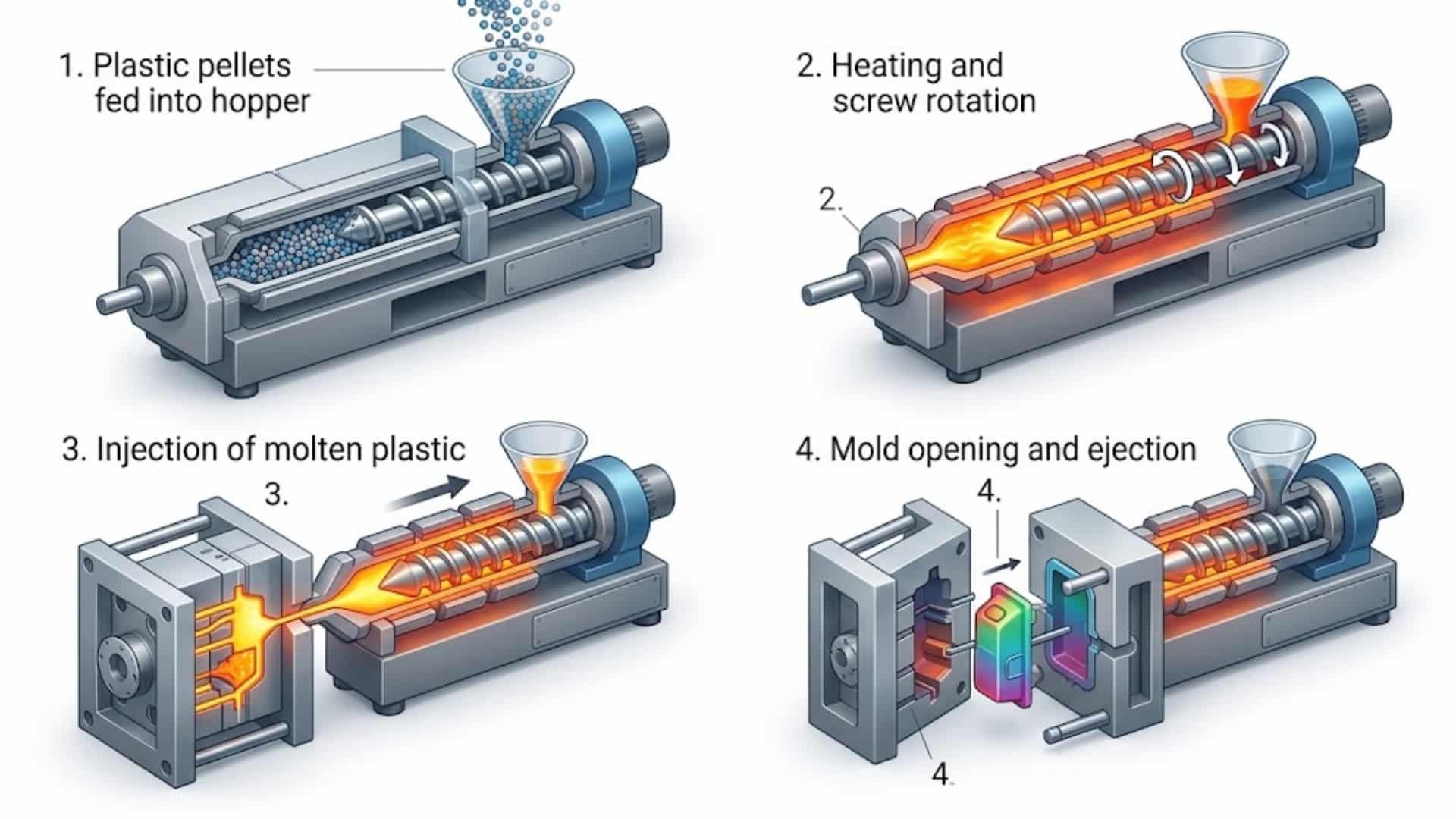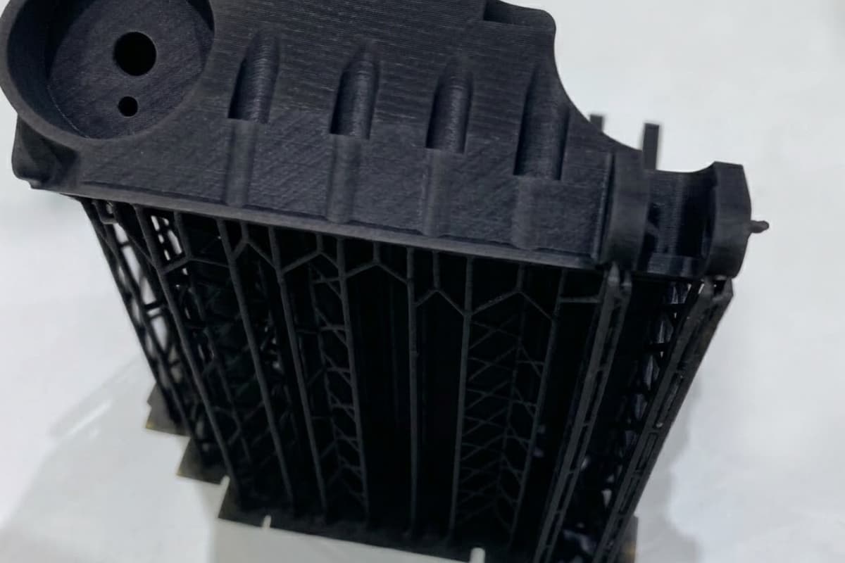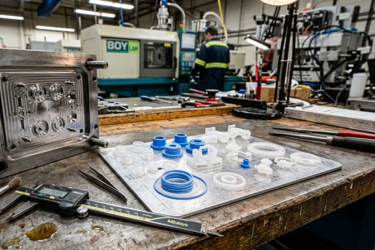

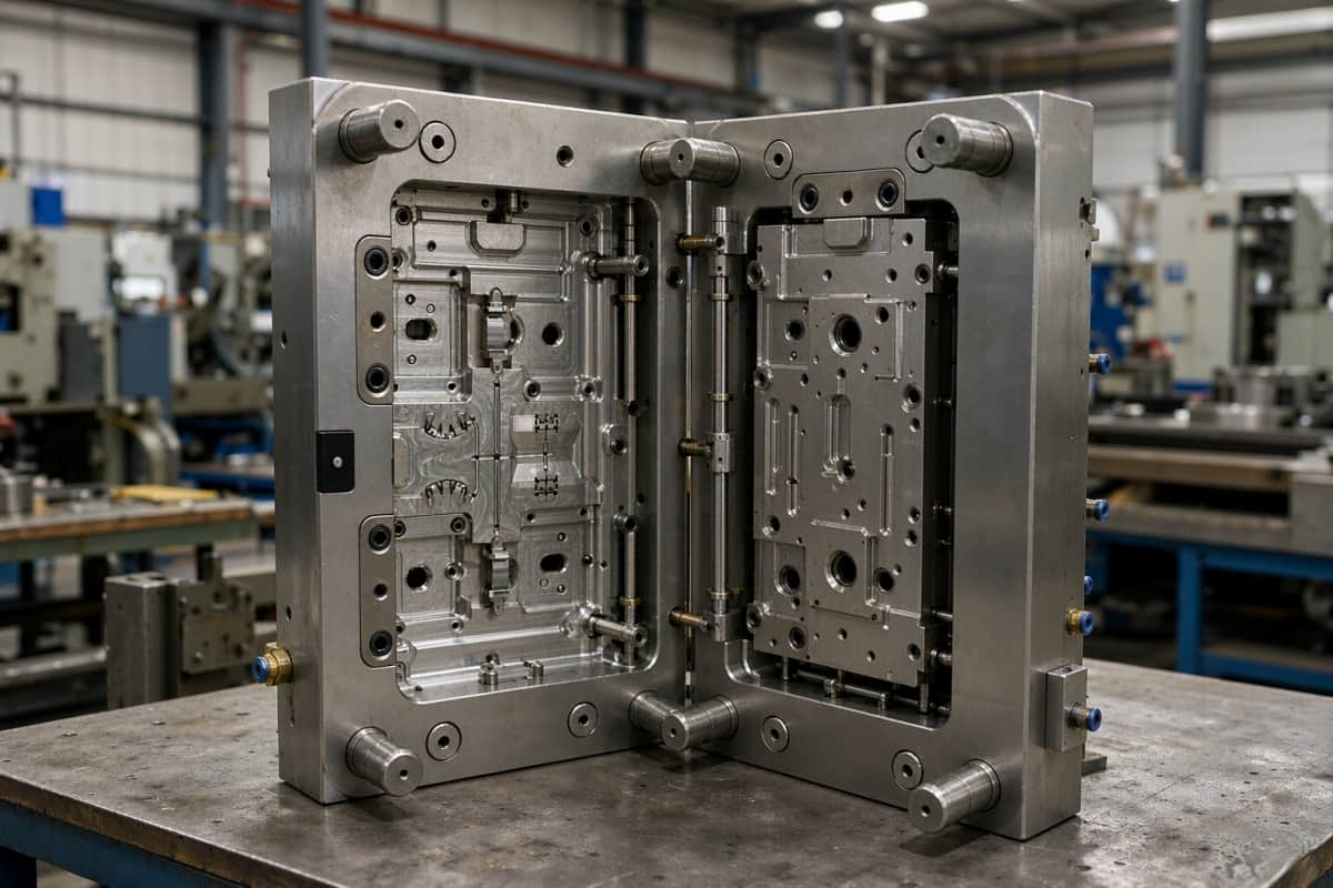
The gate is the smallest feature in an injection mold, and the one that decides most of what follows: how the part fills, where weld lines land, how much shear the material sees, and what your operator has to do to the part after it drops from the machine. Pick the wrong gate type and no amount of process tuning will fix the result. This guide compares the eight gate types used in production molds, gives sizing rules you can check against a supplier’s quote, and ends with a selection chart you can apply to your own part.
What a Gate Actually Does
The gate is the narrow passage where molten plastic leaves the runner system and enters the cavity. Because its cross-section is the smallest in the whole feed system, three things happen there: the melt accelerates and picks up shear heat, the gate freezes first when packing ends, and — after the part is ejected — the gate leaves a mark where it connected. Every gate decision is a trade-off among those three facts.
Gate type is closely tied to where the parting line runs, because that is where most gates are machined and where the mold opens. It also interacts with wall thickness: the gate must be large enough to keep packing pressure flowing until the thickest wall section has frozen, or the part will sink.
The 8 Gate Types at a Glance
| Gate Type | Best For | Typical Size | Degating | Tooling Cost |
|---|---|---|---|---|
| Sprue (direct) | Single-cavity, thick parts | Ø 3–10 mm at part | Manual cut | Lowest |
| Side / edge | General parts, non-cosmetic edge | 0.5–0.8 × wall depth | Manual or auto | Low |
| Fan | Wide, flat parts | Depth 0.5–0.8 × wall | Manual / machining | Medium |
| Tab | Transparent & glossy parts | Tab ≈ 6 mm wide, 75% wall | Manual cut | Medium |
| Pin-point | Small parts, 3-plate molds | Ø 0.8–2.0 mm | Automatic | High |
| Submarine (tunnel) | Auto-degating, hidden gate | Ø 0.8–2.0 mm | Automatic | Medium |
| Cashew (banana) | Gating on an inside surface | Ø 0.8–1.5 mm | Automatic | High |
| Hot runner (valve) | High volume, multi-cavity | Ø 0.5–2.0 mm valve | None needed | Highest |
The 8 Gate Types in Detail
1. Sprue (Direct) Gate
The sprue gate feeds the melt straight from the machine nozzle into the cavity — there is no runner at all. It is the cheapest and least restrictive option, delivers maximum packing pressure, and suits heavy, single-cavity parts such as buckets, housings, or thick structural components. The trade-offs are all cosmetic and practical: it leaves the largest gate scar of any type (often Ø 3–10 mm at the part), and because the sprue freezes last, cycle time is set by the sprue rather than the part. The sprue is cut off flush, and the area is usually hidden on the inside face or machined afterward.
2. Side (Edge) Gate
The side gate enters the part from the parting plane, on an edge or side wall. It is the default choice for two-plate production molds because it is cheap to machine, easy to modify (moldmakers can enlarge it in minutes during T1 trials), and fills predictably. Depth is typically 0.5–0.8 × wall thickness, width 2–3 × depth, with a land length of 0.5–1.0 mm. The main limitations: the gate scar sits on an outside surface, so it must be placed on a non-cosmetic edge, and filling pressure is higher than with a sprue gate because the melt takes a 90° turn.
3. Fan Gate
A fan gate is a side gate that widens from the runner toward the cavity, spreading the melt across a broad front. It is the standard answer for wide, flat parts — panels, covers, laminated sheets — where a point gate would leave a visible flow front, differential orientation, and warp. By distributing the flow evenly across the part width, the fan gate reduces orientation-driven warpage and keeps the fill balanced, applying the same wall and flow principles as our DFM design guide. The cost is post-processing: the wide tab must be machined or cut off, and the scar runs along an entire edge.
4. Tab Gate
A tab gate adds a small sacrificial tab between the gate and the part. The melt jets into the tab first, stalls, and then flows into the cavity as a smooth front — which is exactly why transparent parts (PC, PMMA, clear ABS) use it. Gated directly, these resins jet, and jetting shows up as visible ripples and stress marks near the gate. Tab width is typically around 6 mm with a thickness near 75% of the wall. The tab is removed after molding, so the part pays for it in a secondary cutting operation and a slightly longer cycle.
5. Pin-Point Gate
The pin-point gate is a Ø 0.8–2.0 mm restriction reached through a runner in a three-plate mold. When the mold opens, the gate is sheared off automatically, leaving a tiny nub that is barely visible — often acceptable on a visible face with no finishing at all. It suits small, multi-cavity parts and any program where degating labor must be eliminated. The price is mold complexity: a third plate, more steel, and higher tooling cost. It is also the most shear-aggressive gate on this list, so it is a poor match for shear-sensitive or highly filled resins.
6. Submarine (Tunnel) Gate
The submarine gate drops below the parting line at an angle of roughly 30–45° and enters the cavity on its underside or inner face. Because the gate is sheared by the mold itself as it opens, degating is automatic, the gate scar sits where nobody sees it, and the part needs no hand work. It is the workhorse for high-volume consumer parts molded in two-plate molds. Restrictions apply: the gate is machined into the moving half, repair is harder than an edge gate, and the entry angle needs clearance on the part — a flat side wall with no undercut-adjacent surface may not leave room for it.
7. Cashew (Banana) Gate
The cashew gate is a curved tunnel gate that arcs under the parting line so it can feed the inside of a hollow or box-shaped part — the one surface a conventional gate cannot reach without an undercut. Degating is automatic and the scar hides inside the part. It is the most expensive gate to machine on this list and the hardest to modify after T1, so it earns its place only when gate location genuinely matters: parts where the outside must be flawless and the inside can carry a small nub, such as housings, shaver bodies, and cosmetic enclosures.
8. Hot Runner (Valve) Gate
A hot runner system keeps the plastic molten from the nozzle to each cavity, so there is no runner to recover, no cold slug, and no degating step. With valve-gated nozzles, a pin opens and closes each gate on a programmed schedule, which gives independent control of gate-open timing per cavity and leaves a vestige of only 0.1–0.3 mm. For high-volume programs — especially 8-, 16-, and 32-cavity family or stack molds — hot runner gates deliver the lowest cost per part despite the highest tooling cost. The trade-offs: upfront investment, a controller to maintain, and shear-management at the gate tip for sensitive resins. The cost breakdown between cold and hot runner tooling is worth modeling before the quote stage.
How to Size a Gate (and Check Your Supplier’s Numbers)
Gate sizing has two constraints that pull in opposite directions: the gate must be big enough to let packing pressure hold until the part freezes, and small enough to shear off cleanly (or freeze quickly, for hot tips) without damaging the part. Three rules cover most cases:
- Depth (rectangular gates): 0.5–0.8 × wall thickness. Crystalline resins — which shrink more and need longer packing — sit at the top of the range; amorphous resins at the bottom.
- Width: 2–3 × gate depth for a side gate; fan and tab gates are sized to the geometry they serve.
- Land length: 0.5–1.0 mm. A long land increases pressure drop and shear without improving anything — a common mistake in poorly made molds.
Then check the shear rate. For a rectangular gate, the apparent shear rate is γ̇ = 6Q / (w·h²), where Q is the volumetric flow rate in mm³/s, w is gate width and h is gate depth, both in mm. For a round gate it is γ̇ = 4Q / (πr³). If the calculated value exceeds the material’s limit, the gate is too small — expect gate blush, splay, and degradation. Typical limits used in gate design:
| Material | Typical Max Shear Rate (s⁻¹) | Typical Flow Ratio L/t |
|---|---|---|
| PP / PE | 100,000 | 250–300 |
| ABS / SAN | 50,000 | 150–250 |
| PC | 40,000 | 100–150 |
| PMMA | 40,000 | 100–150 |
| PA66 (dry) | 60,000 | 200–300 |
| Rigid PVC | 20,000 | 100–150 |
Worked example: a 60 g ABS part filling in 1.5 s moves about 57 cm³, so Q ≈ 38,000 mm³/s. A side gate of 4 mm × 2 mm gives γ̇ = 6 × 38,000 / (4 × 2²) ≈ 14,300 s⁻¹ — comfortably inside the 50,000 limit. Shrink that gate to 2 mm × 1 mm and the same shot reaches about 114,000 s⁻¹: nearly 2.3× the limit. That is how undersized gates quietly ruin cosmetic surfaces, and it is a number you can demand from a supplier’s DFM report. Confirm exact limits with the material supplier’s grade datasheet — filled and recycled grades differ.
Gate Location Rules That Matter More Than Gate Type
Choosing the wrong location ruins a part even with the right gate type. Location is also one of the main causes of warpage — the gate sets the flow pattern, and the flow pattern sets fiber orientation and the resulting bow. These seven rules catch most location mistakes:
- Gate from thick to thin. Feeding a thin wall first and pushing melt into a thick section leaves sinks and voids where packing cannot reach.
- Design the weld line, don’t accept it. Multiple gates or holes create weld lines — put them on non-critical, non-loaded areas by choosing where the fronts meet.
- Keep scars off cosmetic surfaces. Decide early which surface is the A-side and place gates on the opposite face, inside faces, or edges.
- Gate into a wall, never into open space. A melt stream entering a free volume jets and folds; a tab gate fixes parts you cannot re-gate.
- Mind molecular orientation. A single gate at one end of a long, thin part fills with lower stress than gates at both ends, which fight each other during packing.
- Balance multi-cavity layouts. Naturally balanced runner layouts (H-pattern) keep every cavity identical; artificially balanced layouts shift distances to equalize pressure — workable, but harder to hold tolerances across cavities.
- Leave degating room. If the gate is sheared or cut by robot, the part needs clearance for the cutter path; for manual degating, an operator needs access and a defined cut line.
Gate-Related Defects and Fixes
| Defect at the Gate | Root Cause | Fix |
|---|---|---|
| Jetting (worm-like flow marks) | Melt entering open space at high speed | Gate against a wall, enlarge gate, add tab gate |
| Gate blush / gloss marks | Excess shear, cold melt, rough gate | Enlarge gate, raise melt & mold temp, polish gate |
| Sinks or voids near the gate | Gate freezes before packing completes | Enlarge gate depth, extend packing, check wall design |
| Short shot in far sections | Flow ratio exceeded for the material | More gates, bigger gate, or thicker flow path |
| Brittle area at gate | Residual stress, cold slugs | Add cold slug well, reduce shear, anneal if needed |
| Flashing at gate | Gate oversized, clamping force marginal | Reduce gate size, verify clamp tonnage |
Most of these are diagnosed and corrected during T1 sampling, not after the mold ships. The defect prevention guide lists the process-side causes that overlap with gate issues.
Degating: What Each Gate Leaves Behind
Post-molding work is part of the piece price, so it is worth knowing what each gate leaves. Sprue, fan, tab, and diaphragm gates are removed by hand or machining, and the cut area may need light finishing. Pin-point, submarine, and cashew gates shear automatically during mold opening — no labor, but a small nub (typically 0.3–1.0 mm high) remains on the part. Hot runner valve gates leave the cleanest result, 0.1–0.3 mm, and nothing to cut. If your drawing specifies a flush or recessed gate mark, that requirement alone may decide the gate type — and it belongs in the tolerance and appearance specification you hand to suppliers, not in an email after tooling starts.
Gate Selection Chart
| Your Part Looks Like… | Start With… | Why |
|---|---|---|
| Single heavy part, low volume | Sprue gate | Max packing, cheapest mold |
| General part, cosmetic A-side | Side gate on non-cosmetic edge | Cheap, tunable, predictable |
| Wide flat panel | Fan gate | Balanced flow, less warp |
| Transparent or high-gloss part | Tab gate | Prevents jetting |
| Small part, multi-cavity, no hand work | Pin-point or submarine | Auto-degating |
| Box housing, gate must hide inside | Cashew gate | Reaches the inside face |
| High volume, many cavities | Hot runner valve gate | Lowest cost per part, cleanest scar |
These are not theoretical choices — they are the decisions made on every production tool. See how they are applied across our injection molding services.
Key Takeaways
- The gate controls fill pattern, weld-line location, shear stress, and post-molding labor — it is a design decision, not a moldmaker detail.
- Gate depth is set by wall thickness (0.5–0.8×), but shear rate against the material limit is the check that actually prevents cosmetic defects.
- Automatic-degating gates (pin-point, submarine, cashew, hot runner) trade tooling cost for labor savings — the crossover depends on volume.
- Gate location rules (thick-to-thin, weld-line placement, scar visibility) matter more than the type itself.
- Put gate-mark requirements in the drawing and specification before tooling — changing gate location after steel is cut means a new gate insert or a new mold.
FAQ
What is the difference between a gate and a runner?
The runner is the channel that carries melt from the sprue toward each cavity; the gate is the final, narrow restriction where the runner meets the part. The runner distributes, the gate meters and freezes.
Which gate type gives the best surface finish?
Hot runner valve gates leave the smallest mark (0.1–0.3 mm) and no runner scar. Among cold runner gates, pin-point and cashew gates leave the least visible marks; fan and tab gates leave the largest scars but the best flow appearance on transparent parts.
What happens if a gate is too small?
Shear rate exceeds the material limit, causing gate blush, splay, and degradation near the gate; packing becomes marginal, so sinks and voids appear in thick sections; and filling pressure climbs, which loads the clamping system.
Can gate location be changed after the mold is cut?
Enlarging an existing gate is routine. Moving it is not: the old gate must be welded or plugged and a new one machined, which disturbs the steel around the cavity and often restarts T1 validation. Locate the gate before tooling is cut.
Does gate size affect cycle time?
Yes, in two ways. A small gate allows earlier gate freeze-off, so packing is short — but risks sinks. In cold runner molds, the sprue and runner often cool slower than the part and set the cycle; a hot runner removes that constraint entirely, which is one reason high-volume molds adopt it.
Gate type and location belong in the DFM conversation, not after the mold is quoted. Contact our engineering team with your part drawing — we will review wall thickness, gate options, and degating requirements before any steel is cut, and you can see the full process scope on our mold fabrication services page.