
Shorts, flash and burns show up on the first shot and get fixed within the hour. Warpage is different. It can appear a day or two after molding, and it rarely traces back to one mistake — design, tooling, material and process all contribute. Below: the four mechanisms, how to predict the distortion before steel is cut, and what can be fixed at each stage.
What Warpage Actually Is
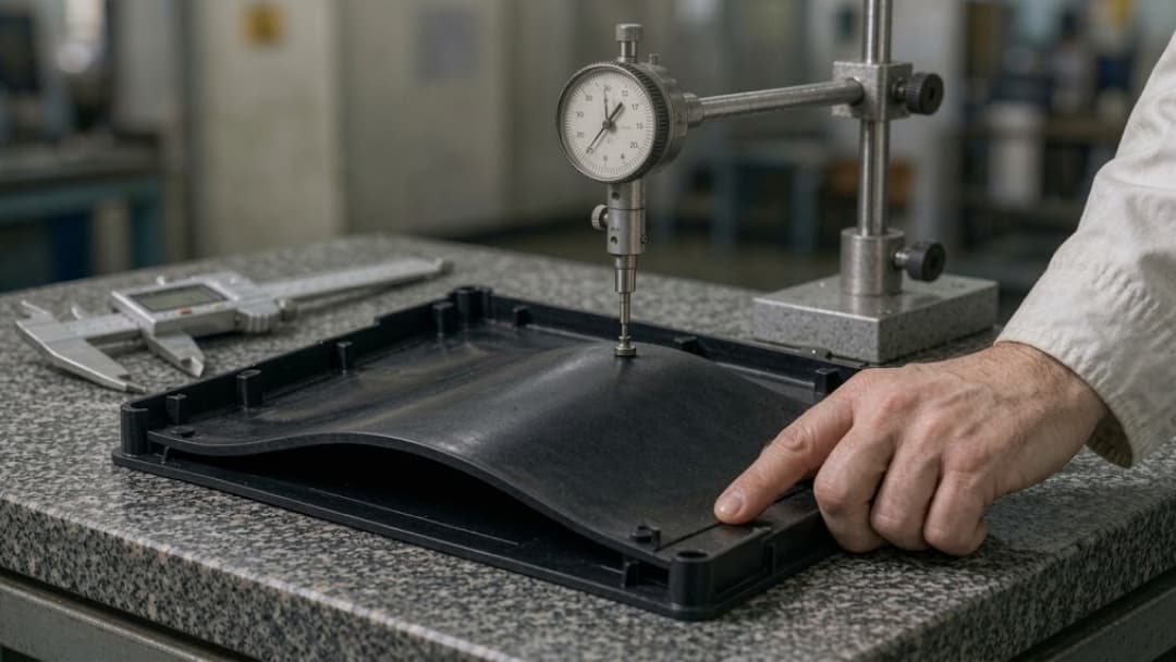
Warpage is out-of-plane distortion caused by differential shrinkage: some regions of the part — or some directions within one region — shrink more than others, and the part bows as the geometry absorbs the difference. It is not sink marks. A sink is a local depression where packing could not feed a thick wall. Warp is a global shape change, and a well-fed part can still warp.
The distinction decides the fix. A sink needs more packing at one spot. Warp needs shrinkage made uniform — across the part, through the wall, and along versus across the flow direction.
The Four Causes of Warpage
| Cause | Mechanism | Typical Signature |
|---|---|---|
| Differential shrinkage (geometry) | Thick sections shrink later and more than thin ones | Bow around a boss or rib; corners pulling in |
| Differential cooling (tooling) | Core and cavity surfaces run at different temperatures | Part cups toward the hotter side, same direction every shot |
| Molecular / fiber orientation | Shrinkage along flow differs from cross-flow | Long parts bow along the flow axis; filled resins worst |
| Residual stress (process) | Stress frozen in by packing gradients, eager ejection | Distortion appears or grows after ejection or in service heat |
1. Differential Shrinkage from Geometry
PP, PE and POM shrink 1–3% as they crystallize; ABS and PC shrink 0.4–0.8%. Wherever wall thickness changes, the thick area shrinks more, and later, than the thin area next to it. A heavy boss on a flat panel or an abrupt rib-to-wall transition will pull the surrounding geometry out of plane even with perfect tooling. The fix is the same one that prevents sinks: uniform wall thickness, gradual transitions, ribs instead of mass.
2. Differential Cooling from the Mold
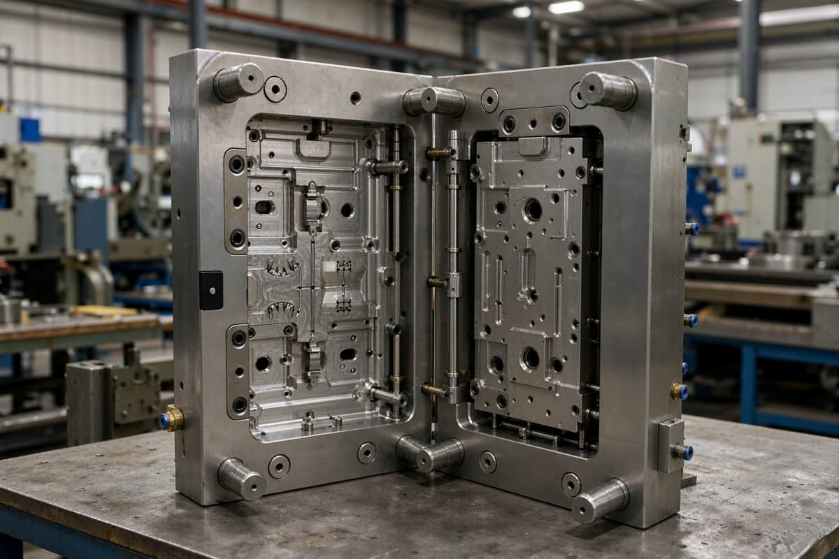
When the cavity side runs hotter than the core, one skin freezes first and the part cups toward the hot side. The direction of the bow is the diagnostic: if every part cups the same way, check mold temperature before anything else. Probe the steel surface, not the controller setpoint. Keep the core–cavity difference within about 5–10 °C on flatness-critical parts, and make sure cooling channels follow the part rather than the plate grid. Where conventional channels cannot reach, conformal cooling is the tooling-level answer.
3. Molecular and Fiber Orientation
Filling aligns polymer chains — and glass fibers — with the flow direction. Aligned material shrinks less along the flow and more across it. Unfilled ABS barely shows the effect. PA-GF grades show it brutally: a flat panel gated at one end dishes across its width; a center-gated disc becomes a saddle. The counters are symmetry, two balanced gates instead of one, or a mineral-filled grade that trades some stiffness for flatness.
4. Residual Stress from the Process
Packing pressure is highest at the gate and decays toward the flow end, so different regions freeze at different densities. The locked-in stress relaxes later — during annealing, assembly, or a summer on a car dashboard. Excessive packing, low melt temperature, and ejecting parts too hot all add to it. When a part is straight at the machine and bent the next morning, that is residual stress, not bad luck.
How to Predict Warpage Before Tooling
Moldflow-style simulation computes anisotropic shrinkage and predicts the deformed shape. Use it to compare options — gate A against gate B, rib layout 1 against 2 — and to catch gross problems before tooling. Do not trust absolute millimeter predictions: they are only as good as the material’s shrinkage data, and filled or recycled grades often have thin data. Ask which grade the simulation used, and run the same grade in production.
The cheapest check needs no software. On the drawing, flag every thick-to-thin transition, every flat area larger than about 100 × 100 mm, and every long flow path on a filled resin. That is where warpage claims come from. Give those features a flatness tolerance now, as part of the dimensional specification — not after T1.
Fixes by Stage: Design, Tooling, Process
| Stage | Fix | Mechanism Addressed |
|---|---|---|
| Design | Uniform wall, ribs instead of mass, gradual transitions | Differential shrinkage |
| Design | Symmetric geometry and gate layout | Orientation imbalance |
| Design | Balanced stiffening on both faces of large flat areas | Global bow |
| Tooling | Balanced cooling channels; core/cavity ΔT ≤ 5–10 °C | Differential cooling |
| Tooling | Gate type and location | Orientation |
| Tooling | Conformal cooling in deep-cored regions | Differential cooling |
| Process | Tapered packing profile, adequate but not excessive | Residual stress |
| Process | Warmer, balanced mold temperature | Cooling + stress |
| Process | Longer cooling time or post-mold fixturing | Stress relaxation |
Gate location is the strongest tooling lever. The gate creates the flow pattern; the flow pattern creates orientation. Moving a single end gate to two balanced gates halves the bow on many filled parts, and switching a center gate to a side gate changes the distortion direction entirely. The options and trade-offs are in our gate types guide. Decide at DFM — moving a gate after tooling means new steel.
One reflex to kill: do not cool the mold down to fix warp. A colder mold freezes the skin faster and locks in more stress, so the part looks straighter at the machine and bends by the next morning. For a warping part, work in this order: probe mold surface balance, retune the packing profile, extend cooling or fixture the parts after ejection — and only then touch steel.
Material Choice and Warpage Risk
| Material | Typical Mold Shrinkage | Anisotropy | Warpage Risk |
|---|---|---|---|
| PP (unfilled) | 1.2–2.5% | Moderate | High |
| HDPE | 1.5–3.0% | Moderate | High |
| POM | 1.8–2.5% | Low–moderate | High |
| PA66 (unfilled) | 1.0–2.0% | Moderate | High |
| PA66-GF30 | 0.3–0.5% flow / 0.8–1.1% cross | Very high | Very high |
| ABS | 0.4–0.7% | Low | Moderate |
| PC / PC-ABS | 0.5–0.7% | Low | Moderate |
| PMMA | 0.3–0.8% | Low | Low–moderate |
Two patterns matter. The high-shrinkage resins — PP, PE, POM, PA — warp often but predictably. Glass fiber does not reduce warp risk; it redirects it. Total shrinkage drops, but the flow-to-cross-flow gap widens, which is why a glass-filled panel can bow worse than the same part in ABS. When flatness dominates, compare grades with anisotropy in mind — our engineering plastics guide covers the trade-offs — and confirm against the specific datasheet, since fillers, colorants and regrind all shift the numbers.
How Warpage Is Measured and Specified
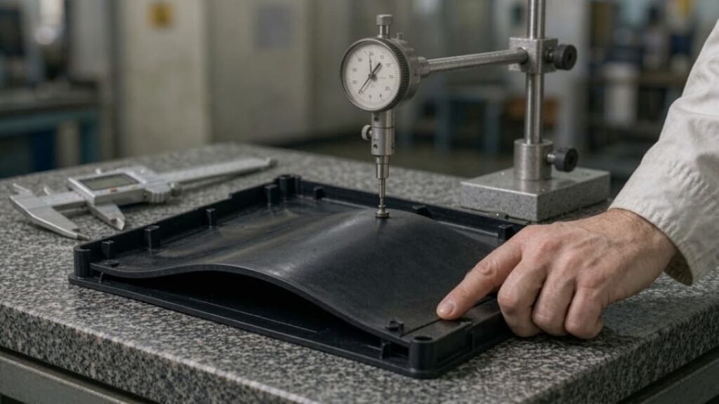
Most warpage disputes are measurement disputes, not molding failures. Measure after 24–48 hours at room conditions — post-mold shrinkage keeps moving well past ejection. State the measurement condition on the drawing: free-state on a surface plate and constrained in assembly fixtures can differ by more than the tolerance itself. And specify flatness as a GD&T zone, not the words “should be flat”. What is achievable depends on material and size, as covered in our tolerances guide.
A quick check during development: fixture freshly molded parts in their assembly orientation for 48 hours, then re-measure. If the shape drifted beyond the flatness zone, packing or ejection temperature needs attention before those parts ever see service heat.
Key Takeaways
- Every warp fix works by making shrinkage uniform — across the part, through the wall, and between flow directions.
- Read the signature: bow toward thick sections = geometry; consistent cup toward one side = thermal; bow along flow = orientation; drift after molding = residual stress.
- Gate location is decided at DFM, not after T1 — moving it later means new steel.
- A warmer, balanced mold usually beats a colder one on final flatness.
- Measure at 24–48 hours, in a stated fixturing state, against a flatness zone on the drawing.
FAQ
Can warped parts be corrected after molding?
Annealing or press-fixing can flatten parts, but the stress relaxes again in service heat. These are containment measures, not fixes. Real correction happens in design, tooling or process — in that order of cost.
How much warpage is acceptable?
Whatever the assembly function allows. A cosmetic panel that snaps into a housing may need 0.5 mm over its length; a structural bracket may tolerate several. Set the number on the drawing before tooling, not during a dispute.
Does higher packing pressure reduce warpage?
Often the opposite. Higher packing widens the pressure gradient between gate and flow end and freezes more stress into the part. A tapered profile tuned at T1 beats a flat, high-pressure profile.
Why do glass-filled parts warp more than unfilled ones?
Fibers align with the flow and restrain shrinkage in that direction, while cross-flow shrinkage stays high. The gap — up to 2–3× in PA-GF grades — turns into bow and twist on cooling. Mineral-filled grades trade stiffness for much better flatness.
How accurate is warpage simulation?
Good for ranking designs and catching gross problems. Weak on absolute numbers, because accuracy depends on the material’s shrinkage data. Verify with T1 samples measured after full post-mold shrinkage.
Warpage is cheapest to fix on the drawing and most expensive on the production floor. Send us your part — our DFM review covers wall transitions, gate strategy and cooling layout before tooling starts. See the full scope on our injection molding services and custom molding pages, or contact our engineering team.