
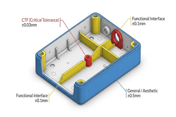
Setting realistic injection moulding tolerances is a balancing act between functional assembly requirements and production economics. Achieving optimal precision requires a clear understanding of polymer shrinkage, part geometry, tool construction, and process capability—rather than directly applying subtractive CNC machining tolerances to moulded plastics.
By establishing clear boundaries between standard and precision tolerances early in the design stage, design engineers can avoid excessive tooling costs, reduce cycle times, and minimize scrap rates.
1. Standard vs. Tight Injection Moulding Tolerances
In plastic injection moulding, tolerance defines the permissible variation across nominal dimensions such as length, diameter, wall thickness, and geometric profiles. Unlike metal machining, plastics undergo extreme thermal expansion, high-pressure injection, and non-linear cooling shrinkage inside the mould cavity.
Tolerance Classifications
- Standard (Commercial) Tolerances: Readily achievable across normal production runs using standard process parameters. Ideal for general housings, covers, and consumer goods without inflating tooling maintenance or scrap rates.
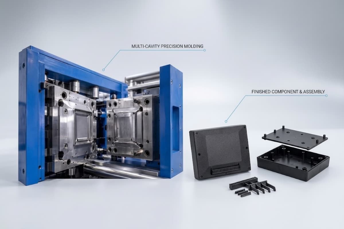
- Tight (High-Precision) Tolerances: Essential for critical assembly interfaces, dynamic sealing surfaces, microfluidics, and tight snap-fits. Requires hardened mould steels, closed-loop machine controls, cavity pressure transducers, and frequent CMM inspections.
Tolerance Capability & Cost Comparison
| Tolerance Class | Typical Dimensional Capability | Tooling & Process Requirements | Typical Applications | Cost Impact |
| Standard (Commercial) | ±0.100 mm to ±0.250 mm | Standard tool steels (P20), standard cooling circuits | Enclosures, brackets, cosmetic covers, structural handles | Baseline tooling & part unit cost |
| Tight (High-Precision) | ±0.025 mm to ±0.050 mm (Critical features only) | Hardened steels (H13, S7), conformal cooling, closed-loop process | Gear trains, multi-part optical mounts, dynamic fluid seals | +30% to +100% tooling & QC overhead |
Pro Tip: Avoid applying tight tolerances across the entire drawing. Reserve high-precision limits strictly for Critical-to-Function (CTF) dimensions, and let commercial block tolerances govern non-critical geometry.
2. The Cost Impact of Over-Tolerancing
Tightening a tolerance limit from ±0.150 mm down to ±0.030 mm causes an exponential cost surge across tooling, production, and quality verification.

Key Drivers of Precision Tooling Costs:
- Tool Steel & Machining Complexity: Demands hardened tool steels (H13, S7, Stainless 420) machined with multi-axis high-speed CNC finishing and micro-EDM rather than standard milling.
- Extended Cycle Times: Slower, strictly controlled packing/holding phases and longer cooling cycles are required to mitigate internal thermal stresses.
- Metrology Overhead: Shifts quality control from batch caliper/optical checks to climate-controlled CMM routines and multi-cavity SPC charting.
Dimension Categorization Matrix
- Critical-to-Function (CTF) Dimensions (±0.025 mm to ±0.050 mm): Dynamic mating surfaces, bearing journals, and O-ring grooves.
- Functional Interface Dimensions (±0.100 mm): Fastener clearance holes, locators, and perimeter snap-fits.
- Non-Critical External Dimensions (±0.250 mm or wider): Drafted side walls, cosmetic radii, internal ribs, and general clearance areas.
3. How Polymer Shrinkage Dictates Achievable Tolerances
Because molten plastic contracts as it cools, the mould cavity must be scaled up to compensate for volumetric shrinkage. The predictability and uniformity of this shrinkage determine the achievable tolerance limits.
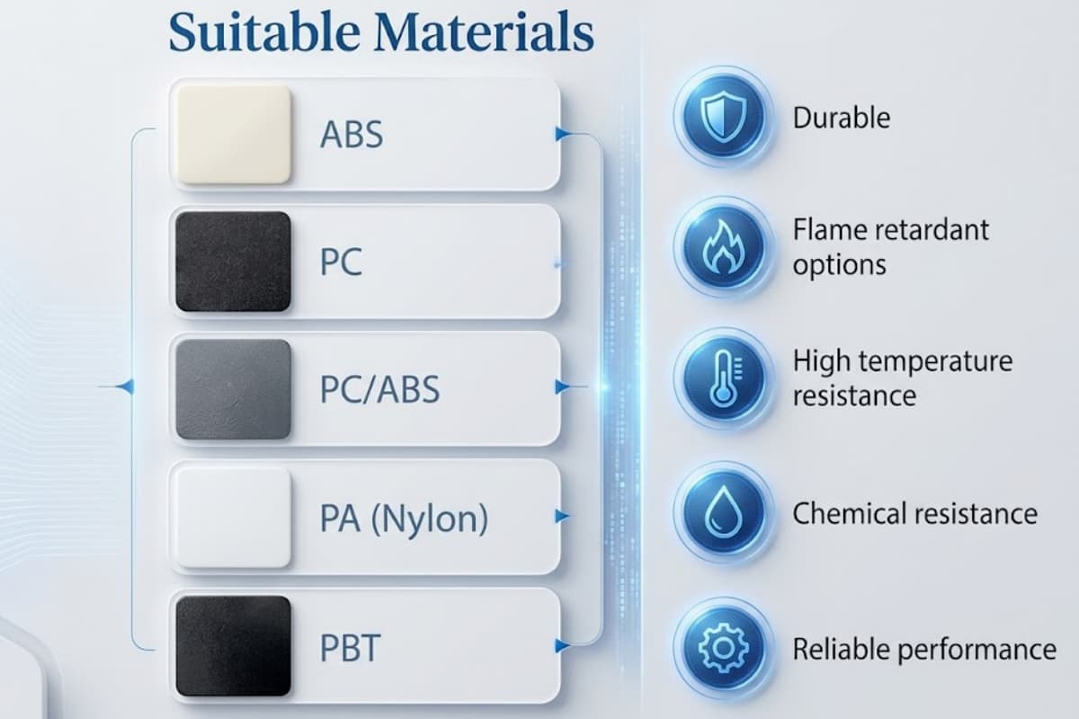
Amorphous polymers (ABS, PC, PMMA, PSU) have low isotropic shrinkage (0.4‑0.7%) and tight tolerance (±0.025‑0.050); semi‑crystalline (POM, PA66, PBT, PEEK) have high anisotropic shrinkage (1.2‑2.5%+) and moderatetolerance (±0.100‑0.150).
Amorphous vs. Semi-Crystalline Resins
- Amorphous Polymers (e.g., ABS, PC, PS): Randomly oriented molecular chains result in low (0.4%–0.8%), uniform shrinkage along both flow and transverse directions. These materials hold tight dimensional tolerances with minimal post-mould warpage.
- Semi-Crystalline Polymers (e.g., POM, PA66, PEEK): Highly organized molecular matrix creates higher shrinkage rates (1.2%–2.5%+). Cooling produces anisotropic shrinkage (shrinking faster across the flow than along it), increasing the risk of dimensional drift and warpage.
- Fiber-Reinforced Polymers (e.g., PA66-GF30): Glass fibers align in the melt flow direction, significantly reducing flow-direction shrinkage while leaving transverse shrinkage higher.
Resin Shrinkage & Tolerance Guide
| Polymer Family | Common Resins | Shrinkage Rate | Tolerance Capability | Primary Dimensional Risk |
| Amorphous | ABS, PC, PC/ABS, PMMA | 0.4% – 0.8% | High (Tight limits feasible) | Sink marks over thick ribs |
| Semi-Crystalline | POM, PA66, PEEK | 1.2% – 2.5% | Moderate (Standard limits preferred) | Post-mould warpage & crystallization |
| Glass-Filled | PA66-GF30, PBT-GF20 | 0.2% (Flow) / 0.8% (Trans.) | Moderate to High | Differential shrinkage & weld-line stress |
4. DFM Rules for Dimensional Tolerance Control
Tooling cannot fully compensate for poor part design. Implementing Design for Manufacturability (DFM) rules stabilizes the injection process:
- Maintain Uniform Wall Thickness: Variations cause differential cooling. Thin walls freeze early while thick sections remain molten, creating sink marks and internal stress. Ribs should be sized to 40%–60% of the nominal wall thickness.
- Apply Adequate Draft Angles: Ensure 1° to 2° of draft per side for smooth surfaces and 3° to 5°+ for textured faces to prevent part drag and ejection distortion.
- Account for Parting Line Mechanical Shift: Dimensions spanning across the mould parting line, slides, or mechanical lifters accumulate tool closure stack-up. Add at least ±0.050 mm to ±0.100 mm to parting line dimensions.
- Optimize Gate Placement: Gate into thick sections first to balance melt pressure across the cavity and ensure uniform volumetric packing.
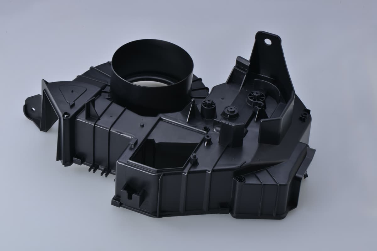
Parting line between cavity and core; moving split vertical; step variance; add ±0.05–0.10 mm stack-up tolerance.
5. Quality Control, Metrology & Inspection Standards

Plastic parts stabilize and release residual stresses over time. Accurate dimensional verification requires strict inspection protocols.
Condition samples at 23 °C/50 % RH for 24–48 h, perform FAI by CMM and 3D optical, verify Cpk ≥ 1.33, then release for mass production.
- Thermal Conditioning: Thermoplastics have high thermal expansion coefficients and hygroscopic properties (e.g., Nylon). Parts must normalize for 24 to 48 hours at 23°C (±2°C) and 50% (±5%) RH before metrology sign-off.
- Metrology Standards: Drawings should reference recognized international standards such as ISO 20457 or DIN 16742 (Tolerance Groups TG1 to TG9).
- Statistical Process Capability: To guarantee repeatability consistency for CTF features, the Cpk must be kept at ≥ 1.33 (or ≥ 1.67 for critical safety items).
Frequently Asked Questions (FAQ)
What is the standard tolerance for injection moulded plastic parts?
Standard commercial injection moulding tolerances typically range from ±0.100 mm to ±0.250 mm for general linear dimensions under 100 mm. High-precision tooling can achieve tolerances down to ±0.025 mm to ±0.050 mm on localized critical features using low-shrinkage amorphous resins.
How does post-mould shrinkage affect final dimensions?
Thermodynamic shrinkage continues for hours after part ejection. Semi-crystalline materials like POM or PA66 undergo post-crystallization for up to 48 hours. Measuring parts immediately upon ejection yields false readings; parts must be stabilized in a climate-controlled environment first.
Can 3D printing validate injection moulding tolerances?
While 3D printing confirms basic form and fit, additive processes do not replicate the anisotropic shrinkage, weld lines, or molecular orientation of injection moulding. Final tolerance verification should be performed using prototype tooling or functional sampling.
Which tolerance standard should be specified on 2D technical drawings?
Industrial plastic drawings commonly reference ISO 20457 or DIN 16742. These standards establish realistic tolerance bands based on resin group, part size, and mould design complexity.
Optimize Your Tooling Budget with Professional DFM Analysis
Balancing dimensional accuracy against piece-part economics requires close collaboration between design engineers and tooling specialists. GoodTech provides engineering-driven injection moulding solutions backed by advanced DFM reviews, mould flow analysis, and certified quality control.
Upload Your CAD Models (STEP/IGES) for a 24-Hour DFM & Quotation Review →