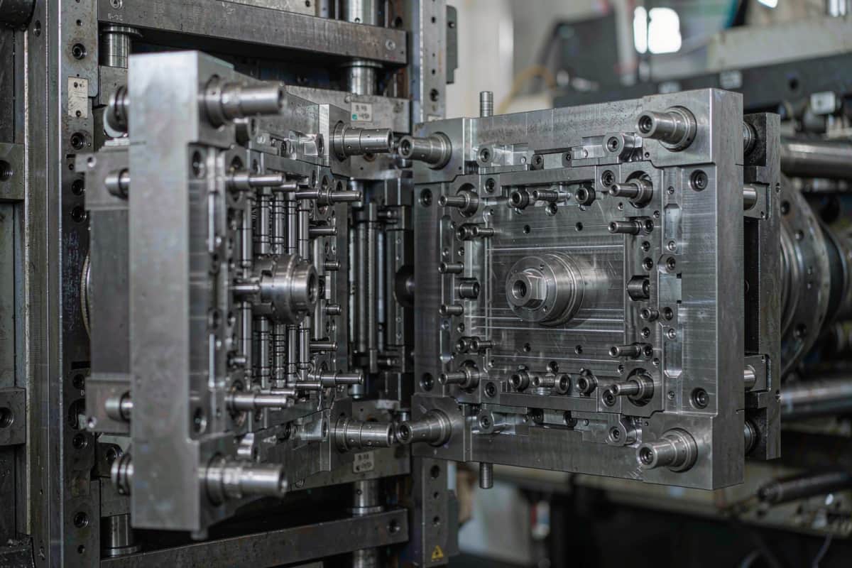

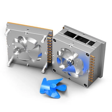
An injection molding parting line is the primary boundary where the two halves of a mold—the core (A-side) and cavity (B-side)—meet and seal under clamping pressure. In injection mold design, determining the location of this interface is the very first step in Design for Manufacturability (DFM).
The placement of the parting line directly controls tooling complexity, the necessity of side-actions, draft angle orientation, cosmetic witness marks, and the risk of flash defects. Placing a parting line incorrectly can turn an economical two-plate mold into an expensive multi-action tool or result in visible cosmetic flaws on Class-A surfaces.
This guide examines the engineering principles behind parting line selection, evaluates core parting line geometries, and provides an actionable DFM framework to optimize part functionality, visual quality, and tooling costs for custom plastic injection molding.
Core Types of Parting Lines in Mold Fabrication
Parting lines are dictated by part geometry, draft orientation, and tooling architecture. Selecting the simplest functional parting line geometry reduces machining difficulty, lowers tool maintenance, and minimizes injection defects.
1. Flat (Planar) Parting Lines
A flat parting line lies entirely on a single two-dimensional plane perpendicular to the mold opening direction. It represents the most economical tooling option because both mold halves can be ground and matched with standard CNC milling and surface grinding operations. Flat parting lines provide uniform clamping force distribution, substantially reducing the risk of flash.
2. Stepped Parting Lines
When a part features at varying heights or internal cutouts, the parting surface steps from one level to another. Stepped designs require precise CNC machining and EDM (Electrical Discharge Machining) to ensure that the vertical transition faces seal tightly. Without adequate draft on the step transitions, vertical shut-offs experience friction wear during repetitive cycles, leading to premature flash along the step edges.
3. Curved and Contoured Parting Lines
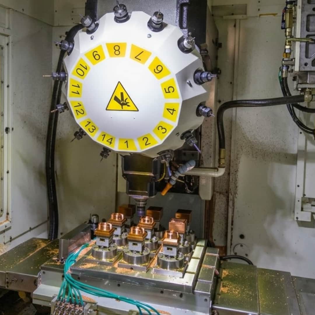
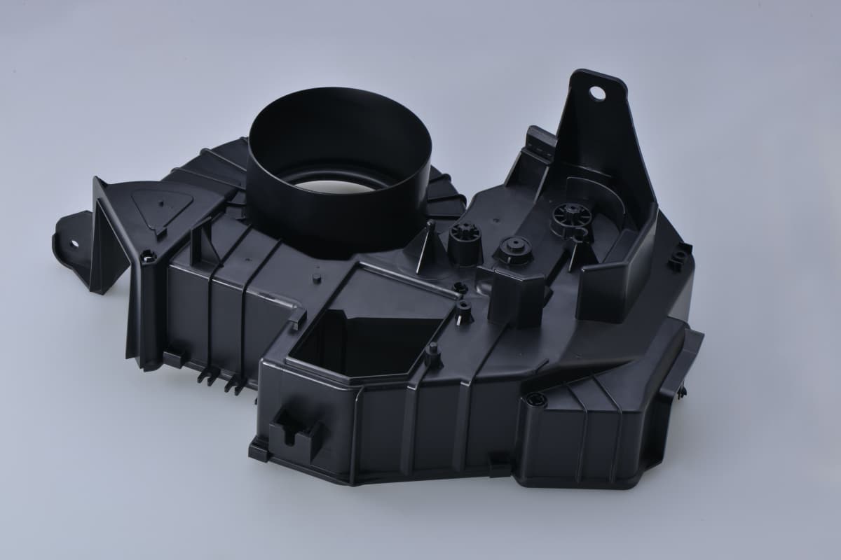
Contoured parting lines follow organic 3D contours across complex surfaces, typical in ergonomic handles and automotive housings. These profiles require multi-axis high-speed CNC milling and manual spotting to ensure a continuous seal across non-planar surfaces. Tooling costs and lead times are higher due to the precision required during precision plastic mold fabrication
4. Complex 3D / Split Parting Lines
Used when parts feature extensive undercuts, threads, or transverse holes, complex parting lines incorporate side-action sliders, lifters, or collapsible cores. While split lines permit advanced geometric freedom, each moving split introduces secondary witness lines and requires tight mechanical alignment to prevent dimensional mismatch.
| Parting Line Type | Geometric Application | Tooling Complexity | Flash Risk | Tooling Cost Impact |
| Flat (Planar) | Symmetrical, box-like, flat-bottomed parts | Low | Low (even clamp pressure) | Baseline / Lowest |
| Stepped | Multi-level enclosures, offset flanges | Moderate | Moderate (requires drafted steps) | +15% to +25% |
| Curved / Contoured | Ergonomic shapes, organic consumer parts | High | High (requires precise spotting) | +25% to +45% |
| Complex 3D / Split | Undercuts, side holes, reverse tapers | Very High | High (multiple moving interfaces) | +40% to +80%+ |
Engineering Rules for Parting Line Selection: A 5-Point DFM Framework
Evaluating parting line placement early during CAD development avoids costly re-tooling and production delays. Applying the following five engineering principles ensures a balance between manufacturing feasibility and part quality.
1. Align the Parting Line with the Maximum Cross-Section
The parting line must sit at the widest perimeter of the part relative to the pull direction. Placing it above or below the widest boundary creates a mechanical trap (undercut), preventing the component from ejecting cleanly from the cavity or core without dedicated side mechanisms.
2. Coordinate Parting Lines with Draft Angles
Draft angles must taper inward away from the parting line in both directions:
- The core side tapers toward the ejection direction.
- The cavity side tapers toward the injection direction.
Locating the parting line along a natural edge or feature transition eliminates reverse-draft traps and ensures a seamless surface transition without visible steps. Validating these draft intersections early through rapid prototyping for DFM validation.
helps verify physical mold release behavior before tool steel is cut.
3. Eliminate or Minimize Side-Actions
Strategic placement of the parting line can eliminate undercut geometries:
- Aligning side holes or snap fits along the main draw direction using pass-through shut-offs allows the mold to core out features without side-action slides.
- Angling the parting line across non-critical surfaces can capture features directly in the stationary or moving halves of the mold, reducing tool maintenance and cycle time.
4. Protect Cosmetic Faces (Class-A Surfaces)
Every parting line leaves a slight witness mark (parting line mismatch or micro-burr). To maintain high visual standards:
- Position the parting line on sharp corners, bottom perimeters, or hidden assembly interfaces.
- Avoid running parting lines across prominent flat cosmetic faces or textured surfaces where witness lines disrupt visual uniformity.
5. Utilize the Parting Line for Natural Cavity Venting
Trapped air and outgassing resin can cause burn marks (dieseling) and short shots. Placing the parting line at the end of the melt flow path allows toolmakers to cut shallow venting channels (typically 0.015 mm to 0.04 mm, depending on the resin viscosity) directly onto the mold parting surface, ensuring rapid air evacuation without creating flash.
Special Considerations: Parting Lines in Overmolding & High-Precision Applications
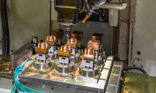
Demanding applications—such as multi-material molding and tight-tolerance technical components—introduce additional constraints for parting line placement.
Shut-Off Surface Design in Overmolding Services
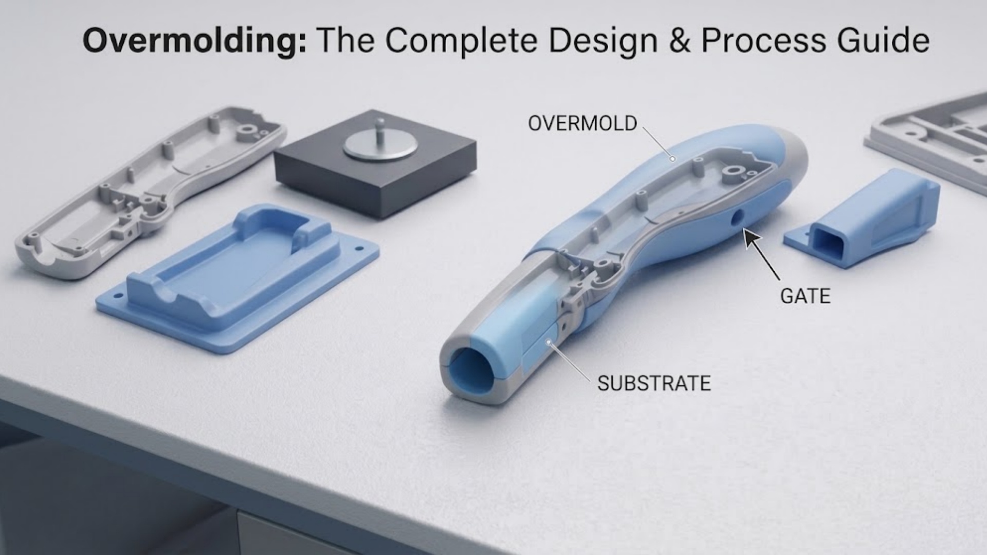
When performing two-shot molding or multi-shot overmolding, the secondary substrate (often a TPE, TPU, or silicone elastomer) must seal firmly against the rigid primary substrate (such as ABS, PC, or PA).
- Hard Shut-Offs: The overmold tooling must compress against the pre-molded substrate with a defined interference shut-off line to prevent elastomeric resin from bleeding across cosmetic surfaces.
- Lead-in Transitions: Parting lines on overmolded grips should terminate in shallow recesses (0.5 mm to 1.0 mm deep grooves) on the substrate to bury the transition edge and prevent peeling under shear stress. These multi-stage tooling dynamics make specialized overmolding services dependent on rigid shut-off tolerances.
High-Precision Tolerancing and Mismatch Control
For micro-molded components, optical lenses, or mating electronic connectors, parting line alignment tolerances must be held within microns. Achieving zero mismatch requires:
- Hardened interlocks and taper locks built directly into the mold base to prevent mold-half shifting under high clamp tonnages.
- In-process dimensional verification using in-house quality inspection equipment such as Coordinate Measuring Machines (CMM) and optical comparators to confirm parting line flatness and shut-off integrity before production runs.
Common Parting Line Defects and Troubleshooting
Improper parting line design or mold machining errors lead to recurring production defects. Identifying the root cause helps determine whether adjustments should be made to processing parameters or tooling geometry.
| Defect | Visual / Functional Manifestation | Root Cause in Mold / Part Design | Corrective Action |
| Flash (Burrs) | Thin plastic excess extending along the parting perimeter | Inadequate clamping force, poorly matched parting surfaces, or excessive injection pressure | Re-spot/machine parting surfaces, increase mold clamp tonnage, or add relief pockets around shut-offs. |
| Parting Line Mismatch (Step / Witness Mark) | Uneven step along the joint line between cavity and core halves | Mold plate shifting, worn guide pins, or non-concentric CNC machining of core and cavity | Install tapered interlocks on mold plates, replace guide bushings, and align CNC datum references. |
| Dieseling / Burn Marks | Charred or discolored edges adjacent to the parting line | Trapped air cannot escape rapidly during fast injection filling | Add or widen parting line vent channels (0.015–0.03 mm depth) at the final filling zone. |
| Drag Marks / Scuffing | Vertical scratches along the part sidewall near the parting line | Insufficient draft angle at the shut-off edge causing abrasive friction during ejection | Increase draft angle (minimum 1.0°–1.5° for smooth surfaces, 3°+ for textured finishes). |
Managing these failure modes requires an engineering-driven approach supported by a rigorous quality system
that validates mold sealing integrity throughout high-volume production cycles.
Parting Line Design Review: Pre-Tooling Checklist for Engineers
Before releasing a 3D CAD model for tooling production, verify each parameter against this engineering checklist:
- Maximum Dimension: Is the parting line placed at the absolute widest perimeter of the part relative to the pull direction?
- Draft Continuity: Does the draft angle pull away correctly from both sides of the parting line without creating back-drafts?
- Mechanism Minimization: Has the parting line been oriented to eliminate unnecessary side-actions, lifters, or complex slides?
- Cosmetic Protection: Is the witness line concealed along a natural edge, hidden seam, or non-visible mating surface?
- Venting Path: Does the parting surface align with the predicted end-of-fill locations to allow effective venting?
- Shut-Off Angle: For stepped or vertical parting transitions, is there at least 3° to 5° of shut-off draft to prevent premature mold wear and flash?
- Material Shrinkage: Has differential material shrinkage been accounted for across the core and cavity halves?
Partner with an Experienced Injection Molding Manufacturer
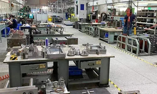
Optimizing your parting line early in the design cycle protects your project budget, shortens lead times, and ensures consistent part quality. As a full-service manufacturing partner specializing in mold fabrication and high precision injection molding services.
, GoodTech provides comprehensive DFM reviews to help your engineering team turn concepts into high-yield production parts.
Key Takeaways
- Placement Dictates Tooling Cost: Placing the parting line at the widest cross-section prevents undercuts and determines whether a tool requires standard two-plate construction or costly side-actions.
- Draft Angle Dependence: Draft angles must always originate at the parting line and taper inward toward their respective mold halves to prevent dragging and part deformation during ejection.
- Cosmetic and Functional Impact: Parting lines leave witness marks. Locating them along natural feature lines or non-critical edges protects Class-A surface aesthetics and prevents flash in functional sealing zones.
- Tooling Longevity: Stepped and contoured parting lines require adequate shut-off angles (typically 3° to 5°) to prevent surface-on-surface friction, galling, and premature tool wear.
Frequently Asked Questions (FAQ)
What is the difference between a mold parting line and a weld line?
A parting line is the physical witness mark created where the two halves of the mold tooling (core and cavity) seal against each other. A weld line (or knit line) is an internal cosmetic or structural defect that occurs when two separate molten resin flow fronts meet and fuse together inside the mold cavity.
How does parting line selection affect mold manufacturing cost?
Flat (planar) parting lines are the most cost-effective because they can be finished with standard 2-axis machining and surface grinding. Stepped, curved, or split parting lines require multi-axis CNC milling, EDM processing, hand spotting, and often side-action mechanisms, which can increase initial tooling costs significantly.
Can a parting line be completely invisible on an injection molded part?
No injection molded part can have a 100% invisible parting line due to micro-clearances between steel components and the physics of high-pressure resin containment. However, skilled toolmakers can minimize its visibility by placing the line along existing geometric edges, textured borders, or non-cosmetic mating faces.
What is the recommended shut-off angle for vertical parting lines?
Vertical shut-off surfaces should feature a minimum draft angle of 3° to 5° (7° or more is preferred when space permits). A zero-degree vertical shut-off causes steel-on-steel friction during mold opening and closing, leading to rapid tool wear and heavy flash.
Contact GoodTech for technical support.
Ready to optimize your component for tooling? Submit your CAD files for an engineer-led DFM review
from GoodTech’s mold fabrication specialists to evaluate parting lines, draft angles, and side-action requirements before cutting steel.