
Overmolding a soft elastomer onto a rigid polycarbonate (PC) substrate sounds straightforward on a DFM checklist. In serial production, it is one of the easiest ways to scrap parts. Polycarbonate has a high glass transition temperature (Tg ≈ 145 °C), high melt viscosity, and low chemical affinity with standard styrenic block copolymers (TPS/SEBS). If the melt cools before wet-out occurs, adhesion fails.
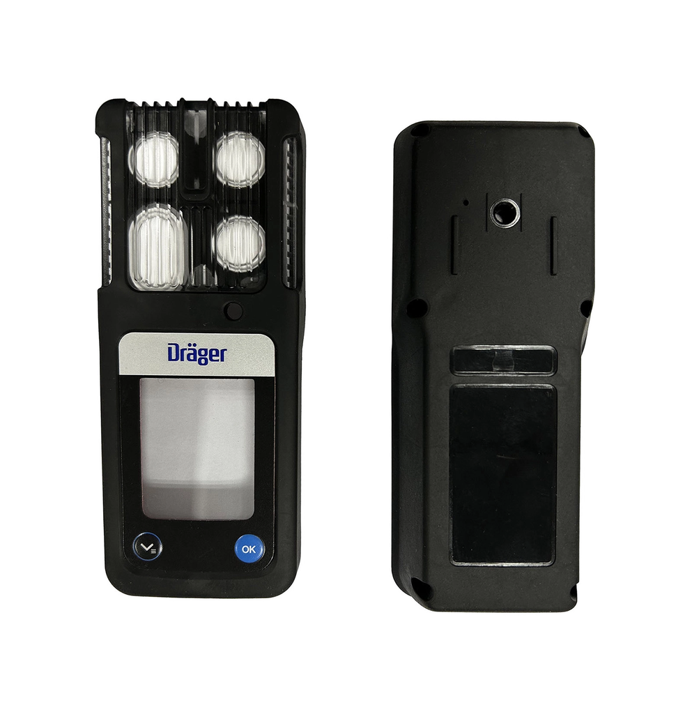
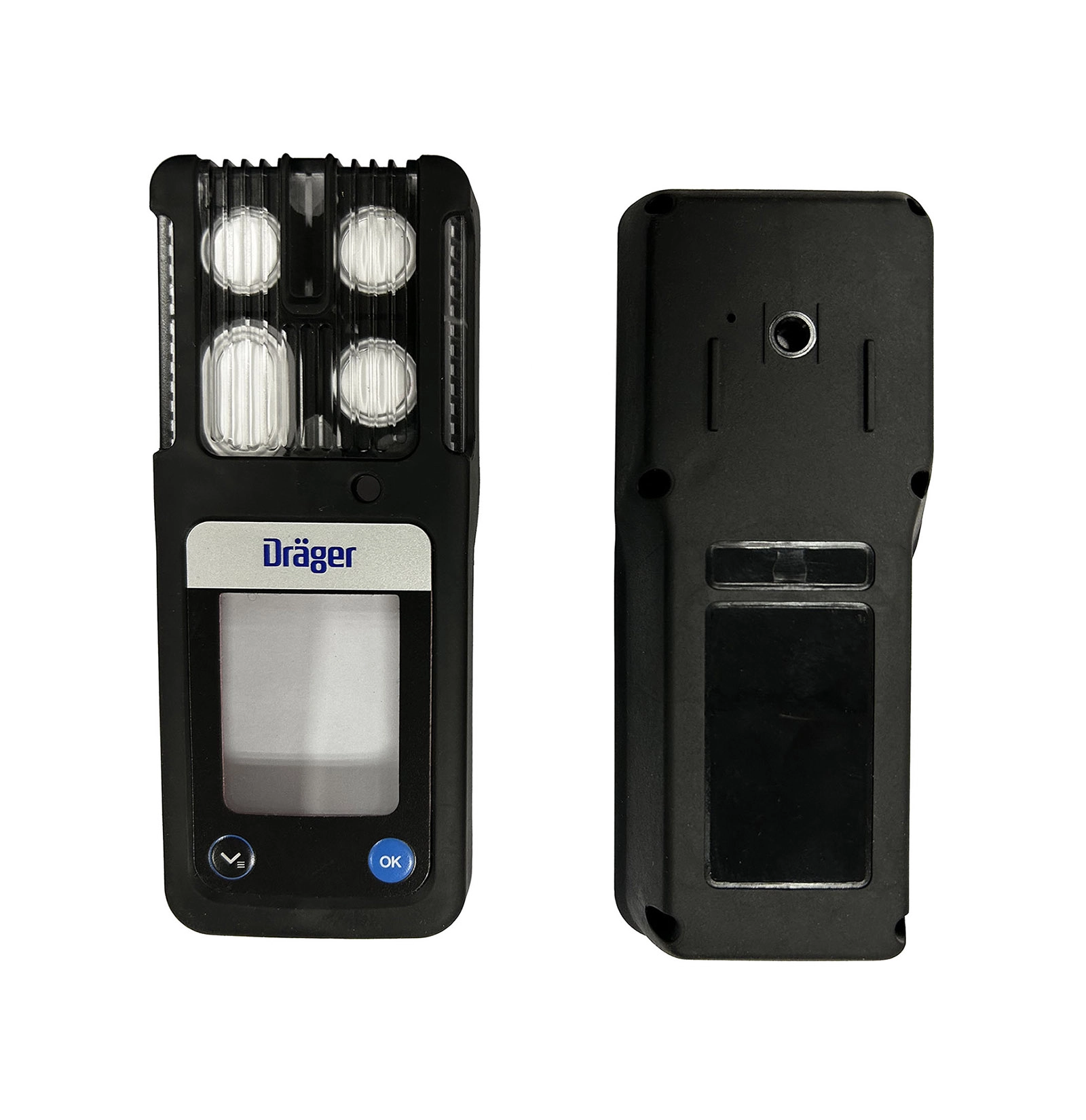
Below is an engineering teardown of how we tuned the tooling, venting, and thermal window for a 190 × 100 × 30 mm portable multi-gas detector enclosure manufactured for Dräger(draeger.com). The part runs on a 200-ton cold-runner press and must withstand continuous exposure from −20 °C to 50 °C alongside repeated 1.5 m drops onto industrial steel grating.
1. Project Baseline & Failure Modes
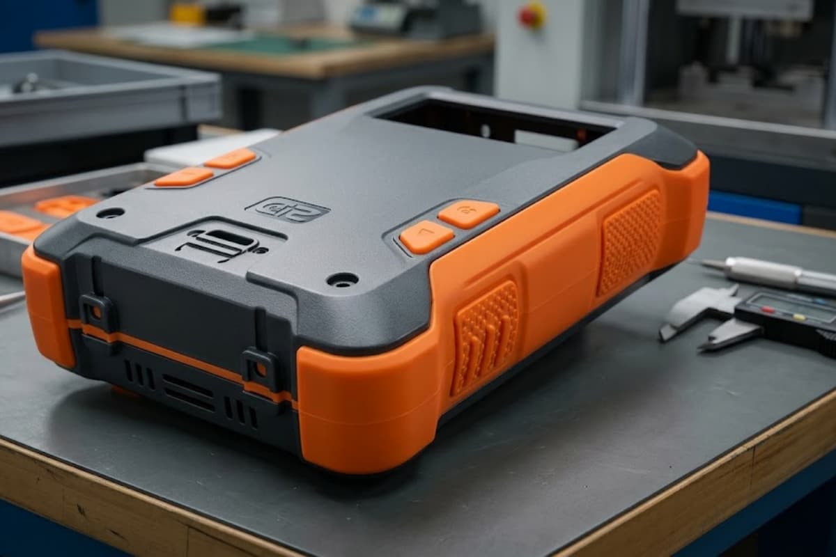
The enclosure uses an unfilled, high-impact PC core designed to protect internal gas sensors and PCB assemblies. Dräger specified a soft-touch TPE overmold for grip, impact damping, and drop protection.
| Parameter | Specification |
|---|---|
| Part dimensions | 190 × 100 × 30 mm |
| PC wall thickness | 1.8–2.2 mm nominal |
| Overmold thickness | 1.2–1.5 mm |
| Tooling | 200-ton, single-cavity, cold runner |
| Drop requirement | 1.5 m, 6 faces, steel drop floor |
| Operating range | −20 °C to +50 °C |
On initial T1 tooling trials, three distinct failure mechanisms surfaced simultaneously:
Delamination under shear (adhesion failure). Unmodified TPE grades failed to achieve molecular interdiffusion with the amorphous PC substrate. Edge peeling was detectable with a simple fingernail pull, and cryogenic drop testing at −20 °C sheared the bond line entirely.
Dead-bond zones from micro-trapped air. Melt travel across the 190 mm envelope caused significant pressure drop. Compressed air trapped against the cold PC substrate created micro-voids at the interface. These voids showed no exterior surface defects but acted as propagation points for bond failure during impact.
Flashing around optical windows. Raising injection pressure to eliminate end-of-stroke short shots forced elastomer melt across the shut-offs around the display window and the four tactile button apertures.
2. Chemical Compatibility: Locking the Resin Grade
Standard SEBS-based TPEs rely on mechanical interlock unless chemically modified. Because this enclosure lacked aggressive undercut features around the perimeter, retention relied entirely on chemical bonding. We evaluated three commercial overmolding formulations modified with maleic anhydride (MAH) and functional polar groups designed to react with polycarbonate’s ester linkages — a comparison method covered in more depth in our TPE and TPU overmolding materials guide.
| Material candidate | Hardness | PC adhesion (90° peel) | Chemical resistance (IPA / oils) | Failure mode |
|---|---|---|---|---|
| Grade A — standard SEBS | 65 Shore A | 1.8 N/mm | Moderate | Adhesive peel (clean separation) |
| Grade B — polar modified | 60 Shore A | 4.2 N/mm | Good | Mixed adhesive / cohesive |
| Grade C — custom functionalized | 65 Shore A | > 6.5 N/mm | Excellent (24 h wipe pass) | Cohesive failure (substrate tears) |
We locked Grade C. Under ASTM D6862 90-degree peel testing, the elastomer tore internally (cohesive failure) rather than releasing from the PC interface.
3. Tooling Modification: Controlled Venting & Melt Front Directing
Venting a 190 mm cold-runner tool requires precise shut-off tolerances; TPE flashes at significantly tighter clearances than engineering thermoplastics.
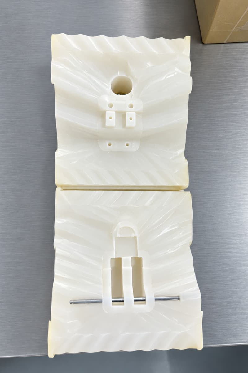
Melt path and venting layout
- Gate: relocated from a center-biased position to a directional end-gate at End A.
- Melt front: a continuous, uniform front advances from End A toward the perimeter, pushing displaced air ahead of the flow rather than enclosing it.
- PC insert shut-offs: seal steps re-ground to 0.008 mm around the four button cores and the main sensor/display window — enough to arrest flow without crushing the pre-molded PC insert. Air in micro-ribs is evacuated through the inserts.
- Parting-line vents: 0.015–0.018 mm depth (0.018 mm nominal), with a 1.0 mm land transitioning into a 0.8 mm relief channel.
- Deep-pocket overflow channels: placed at the far end of the cavity to take the last of the displaced air.
Note: standard 0.03 mm venting used for PC will cause flash with soft TPE. The same tolerancing logic applies to shot-off and draft decisions covered in our overmolding design guidelines.
4. Thermal & Kinetic Processing Window
The bond between PC and TPE is formed within a narrow thermodynamic envelope: the interface must reach sufficient temperature to allow polymer chain entanglement without exceeding the thermal deflection point of the molded PC shell.
Dual-zone tool temperature control
- PC substrate side (cavity/core): held at 50–55 °C to prevent post-mold warpage and relieve internal molded-in stress.
- TPE mold half: maintained at 65–70 °C. A warmer mold wall delays the freezing of the TPE skin, allowing the functionalized elastomer chains to wet out and bond to the PC substrate before vitrification.
Two-stage packing profile
- Stage 1: high-velocity dynamic fill to 95% volume, avoiding flow hesitation marks across the display boundary.
- Stage 2: stepped-down packing pressure (holding at 35 MPa) to pack out the grip ribs while preventing flashing past the 0.008 mm core shut-offs.
5. Inspection & Quality Acceptance
Serial production validation focused on mechanical endurance and interface integrity rather than cosmetic appearance alone.
- Peel adhesion: ASTM D6862 peel testing resulted in 100% cohesive substrate tear — bond strength exceeded the mechanical tensile limit of the 65 Shore A elastomer.
- Environmental and drop testing: complete units survived 6-face, 1.5 m drops onto steel plates at −20 °C without seam delamination or shock transmission to the internal PCB mounts.
- IP sealing and flashing: zero intrusion over optical surfaces and clean parting lines along all tactile switch cutouts, meeting IP67 ingress protection requirements.
Technical Capabilities for Demanding Overmolding Applications
Achieving structural bonds between dissimilar polymers requires tight integration between polymer chemistry, tooling mechanics, and multi-stage process control. The margin between delamination and tooling flash is often less than 15 °C in tool temperature and 0.01 mm in vent depth.
Our engineering team oversees tool design, mold flow analysis, and serial production under ISO 13485 and ISO 9001 standards. If you are developing an enclosure requiring rigid-to-soft overmolding — such as TPE over PC, ABS, or glass-filled polyamides — review our plastic injection molding capabilities or see how we built the Dräger gas detection meter housing. For background on the wider process, start with our complete overmolding guide; for defect signatures and countermeasures, see the overmolding defects and troubleshooting guide. Baseline rules on shut-offs and draft angles are covered in our injection molding guide.