
Overmolding fails at the interface between the substrate and the second material, not in the bulk of either plastic. If your overmolded part is peeling, flashing at the parting line, warping, or showing weak weld lines, the cause is almost always bond-related—material compatibility, substrate temperature, contamination, or gate and shut-off design—rather than a generic molding fault. This guide maps the most common overmolding defects to their root causes and first fixes, and shows how to tell whether the solution is a process tweak or a tool/design change.
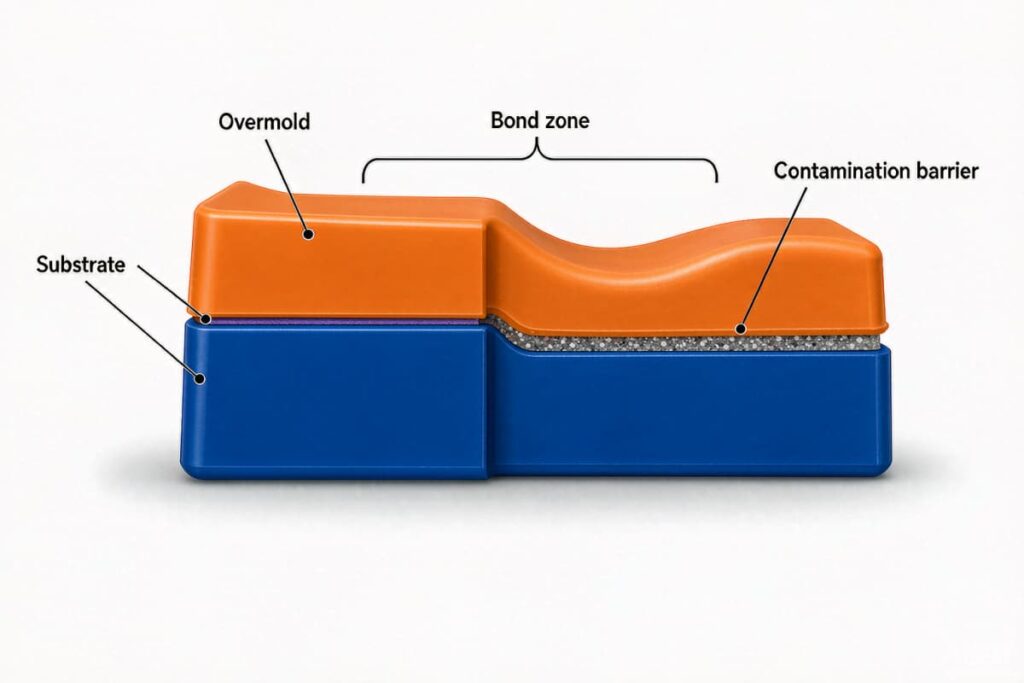
Why Overmolding Fails at the Interface (Not the Material)
Two bonding mechanisms hold an overmold to its substrate: mechanical interlocking (undercuts, texture, through-holes) and chemical bonding (the overmold melt softens the substrate surface so polymer chains entangle across the boundary). Delamination happens when one or both mechanisms are missing.
- A cold substrate freezes the incoming melt before it can wet the surface—no chain entanglement.
- Contamination (oil, mold release, moisture) sits between the materials as a barrier layer.
- An incompatible grade pair cannot diffuse across the interface at all.
The common belief that “just raise the temperature” fixes peeling is wrong for material and contamination causes. Bond strength starts with design and material selection, which is why our overmolding design guidelines on wall thickness and bond strength should be read before tooling.
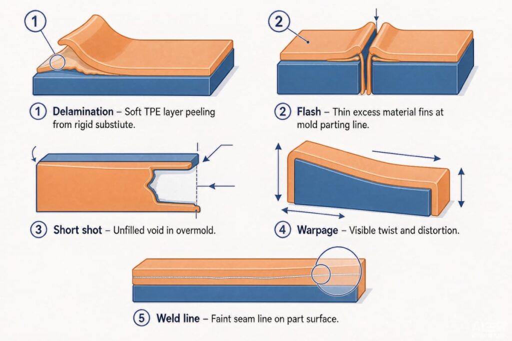
Defect Map: Symptoms, Root Causes, Fixes
| Defect | Root cause | First fix | Prevention |
|---|---|---|---|
| Delamination / weak bond | Incompatible grade, cold substrate, contamination | Pre-heat substrate to 60–80°C; validate pair with peel test | Confirm compatibility; clean substrate |
| Flash at interface | Worn shut-off, excess clamp pressure | Re-cut shut-off surfaces; design tongue-and-groove shut-off | Hardened steel (HRC 52–58) at wear points |
| Short shot (overmold) | Thin sections freeze early | Raise melt temp 10–20°C | Minimum ~1.0 mm wall; redesign thin zones |
| Substrate warpage | Injection pressure too high; thermoplastic softens | Reduce fill rate 20–30%; add core support | Balance fill; support thin substrates |
| Weld line | Converging flow fronts meet | Relocate gate; sequential valve gating | Gate to avoid convergent fronts near bond zone |
| Stress cracking | Rapid uneven cooling, high internal stress | Slow cooling; relax stress | Uniform wall; controlled mold temp |
| Sink on substrate side | Overmold >3.0 mm locally re-softens substrate | Limit overmold to ~2.5 mm; add cooling under thick zone | Uniform thickness; gradual transitions |
| Color bleeding | Pigment migrates at softened interface | Use encapsulated-pigment TPE grade | Select pigment system per pair |
Delamination detail. Pre-heating the substrate to 60–80°C before the overmold shot increases bond strength by 40–70% versus room temperature in tested TPE/ABS pairs (peel rising from about 120 N at 25°C to about 210 N at 70°C), with diminishing returns above 90°C where the substrate itself risks softening. Temperature windows vary by pair: ABS/PC with TPE/TPU typically wants a 65–85°C substrate and 50–70°C mold; PA66 with bondable TPE runs 80–100°C substrate; metal inserts pre-heated 90–120°C (brass 100–130°C) with a 60–85°C mold.
Flash detail. Interface flash accumulates as shut-off surfaces wear from repeated cycling. New molds typically run flash-free for 100,000–200,000 cycles; planned re-cutting of shut-offs every ~150,000 cycles, with hardened steel inserts at high-wear points, extends the interval to 400,000+ cycles.
Weld line detail. Unlike single-material weld lines that are mostly cosmetic, an overmold weld line can leave a bond-free zone where neither flow front contacts the substrate with enough pressure to adhere. Sequential valve gating—gates opening in timed sequence rather than together—removes the convergent front and produces weld-line-free bonds.
These interface issues overlap with general molding faults explained in our common injection molding defects prevention guide, and the industry scenarios are in our overmolding applications guide.
Design Changes vs Process Tweaks
A useful rule from production data: roughly 40% of overmolding defects require a tooling or design change that process adjustment alone cannot fix. Knowing which bucket your defect falls in saves iteration cycles.
- Process-only fixes: substrate too cold (raise pre-heat), short shot from low melt temp (raise 10–20°C), minor warpage from fill rate (reduce 20–30%), trapped air (add vent).
- Design/tool changes required: incompatible material pair (change resin), worn shut-off (repair tool), section thinner than ~0.5 mm (redesign wall), missing mechanical interlock (add knurl/through-hole/undercut).
The design side is covered in the overmolding design guidelines and in our ribs and bosses guide; parting-line and shut-off geometry is in the parting line guide.
Material Compatibility and Surface Prep
Bonding starts with the pair. Polar substrates (PC, ABS) need a compatible polar or bondable elastomer; pairing them with a non-polar TPE without a compatibility agent peels immediately. Beyond grade selection:
- Clean the substrate. Residual stamping oil, cutting fluid, or mold release destroys adhesion. Ultrasonic solvent degreasing, and for metals plasma or flame treatment, raise surface energy so the melt wets and locks.
- Add mechanical interlock. Knurl, groove, or through-holes in the substrate give the overmold a physical anchor when chemical bonding alone cannot carry the service load.
- Control moisture and regrind. Hygroscopic substrates and overmold resins must be dried per the supplier’s condition; moisture causes splay, voids, and weak bonds.
Pairing tables and grade notes are in our TPE and TPU overmolding materials guide.
Process Windows That Control Bond Quality
Once material and design are right, hold these windows:
| Parameter | Effect on bond | Risk if off |
|---|---|---|
| Substrate temperature | Keeps interface above Tg for chain diffusion | Too cold → no wet-out; too hot → substrate softens |
| Melt temperature | Fills thin sections, wets surface | Too low → short shot; too high → degrade/substrate damage |
| Injection speed/pressure | Fills before freeze-off without moving substrate | Too high → flash, substrate shift |
| Packing | Fills interlocks, avoids sink/void | Too low → incomplete retention; too high → distort thin substrate |
| Mold temperature | Surface replication, cooling, ejection | Imbalanced → warpage, stress |
Hot versus cold runner choices affect how consistently you hold melt temperature at the gate—see the hot runner versus cold runner guide. Start from the material supplier’s datasheet window and change one variable at a time, documenting each result.
Validation and Inspection for Production
Visual inspection alone cannot prove a reliable bond. A production validation plan should reflect how the part actually fails:
- Material records: lot, grade, drying, and process logs for both shots.
- Dimensional checks: substrate location, critical rigid features, functional overmold geometry.
- Bond tests: 90° peel (ASTM D903), rubber-to-rigid adhesion (ASTM D429), cross-hatch, or torque/pull-out per a defined specimen and loading direction.
- Functional tests: leak or pressure for integrated seals, compression-set for compressed elastomers, thermal cycling and chemical immersion for the intended environment.
First articles should pass a T1 sample evaluation before release, and suppliers should survive a supplier qualification audit before you commit volume.
FAQ
Can delamination be fixed by raising the temperature? Only when the cause is a cold substrate. If the pair is incompatible or the surface is contaminated, more heat will not bond them—and can damage the substrate. Run a peel test and confirm material and cleaning first.
What is the minimum overmold wall thickness? Around 1.0 mm is a common practical floor; thinner sections freeze before they fill and leave short shots or weak interlocks. Confirm against your specific resin and bond geometry.
How do I test overmold bond strength? Use a 90° peel test (ASTM D903) or rubber-to-rigid adhesion test (ASTM D429), with torque or pull-out where the service load is rotational or axial. Acceptable failure is substrate or elastomer tear, not interfacial separation.
Why does flash appear only after many cycles? Shut-off surfaces wear from repeated clamping; flash grows as the steel-to-steel edge loses its sharp line. Plan shut-off re-cuts and use hardened steel at wear points.
Does two-shot avoid these defects? It shares the same interface physics. Two-shot changes the machine architecture, not the bonding fundamentals—see two-shot versus overmolding and insert versus overmolding.