
Insert molding embeds a pre-made component—usually metal, sometimes ceramic or a second plastic—into a mold cavity and injects molten plastic around it so the two become one bonded part in a single cycle. It is the right choice when you need a thread, electrical contact, bearing surface, or sealed metal feature locked permanently into a plastic body without post-molding assembly. This guide covers how the process works, the design rules that prevent the most common failures (insert shift, hoop-stress cracking, voids), how to pair insert and plastic materials, and when insert molding beats overmolding or two-shot molding for your volume and part geometry.
What Insert Molding Actually Joins (and What It Doesn’t)
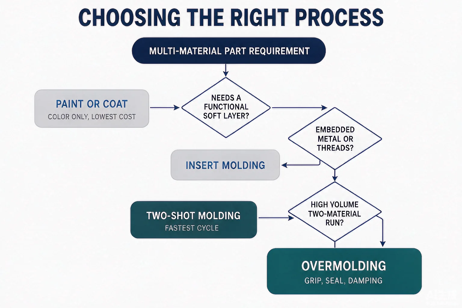
Insert molding, overmolding, and two-shot molding all combine materials, but they solve different problems and carry different tooling costs. Getting the comparison right early saves a costly tooling mistake.
- Insert molding places a finished insert into a single cavity of a single mold, then shoots one plastic shot around it. The insert already exists as a discrete part; plastic only encapsulates it.
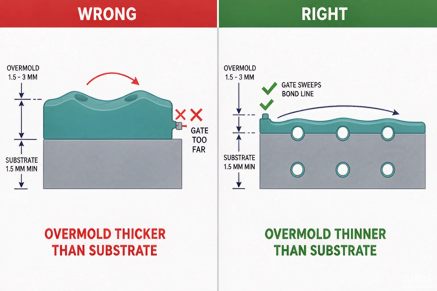
- Overmolding molds a second (usually soft) material onto a substrate that was itself just molded—either in a second shot in the same tool or in a second operation. The substrate is plastic-on-plastic or metal-with-plastic-bonded.
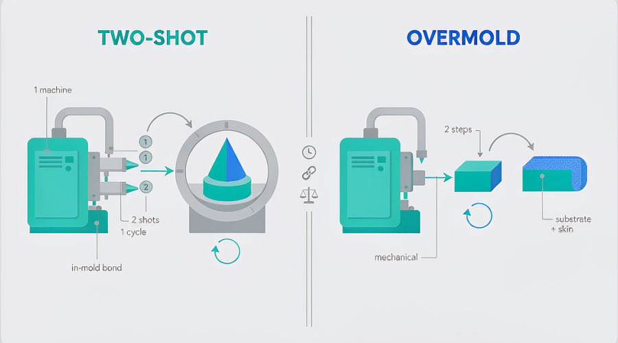
- Two-shot molding runs both materials in one machine and one clamping sequence, rotating the part between cavities. It needs a specialized rotary or transfer machine and a more expensive tool.
The practical distinction: if you already have a precision metal piece (a threaded bushing, a pin, a blade) and want it captured in plastic, insert molding is the direct route. If you want a soft grip fused onto a plastic shell, overmolding fits better. The detailed trade-off between the first two is covered in our comparison of insert molding versus overmolding, and the machine-architecture differences are in our guide to two-shot versus overmolding.
| Process | Interface type | Relative tooling cost | Best volume | Typical part |
|---|---|---|---|---|
| Insert molding | Plastic encapsulates a finished insert | Low–medium | Prototype to high volume | Threaded housings, sensor pins, bushings |
| Overmolding | Soft material bonded to substrate | Medium | Medium–high | Soft-touch grips, seals |
| Two-shot molding | Two plastics in one cycle | High | High | Multi-color, multi-durometer parts |
How the Insert Molding Process Works (Step by Step)
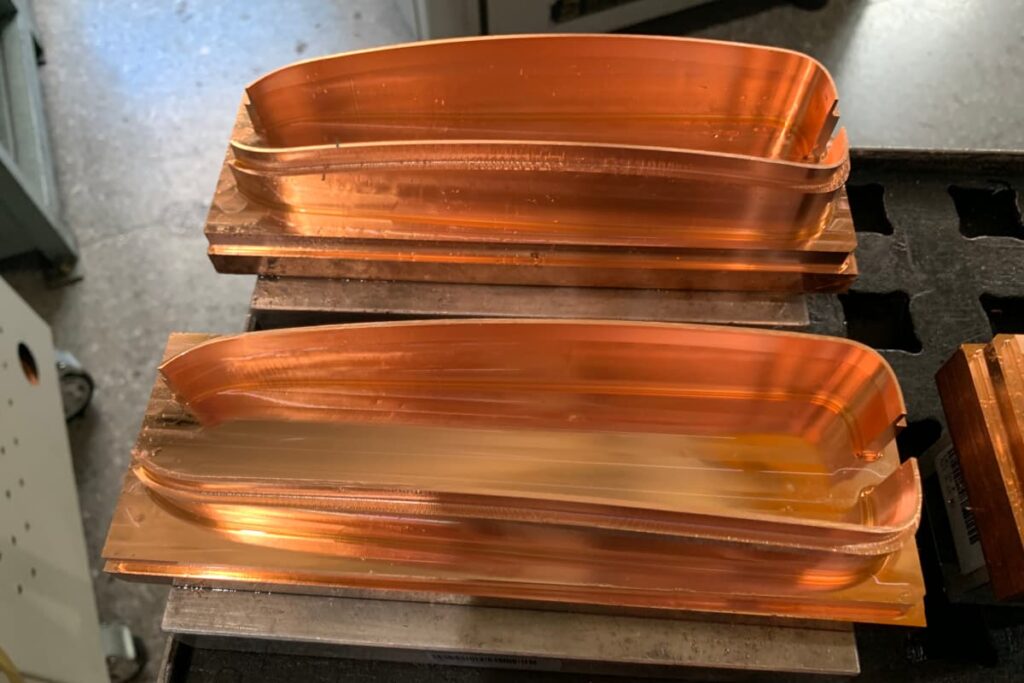
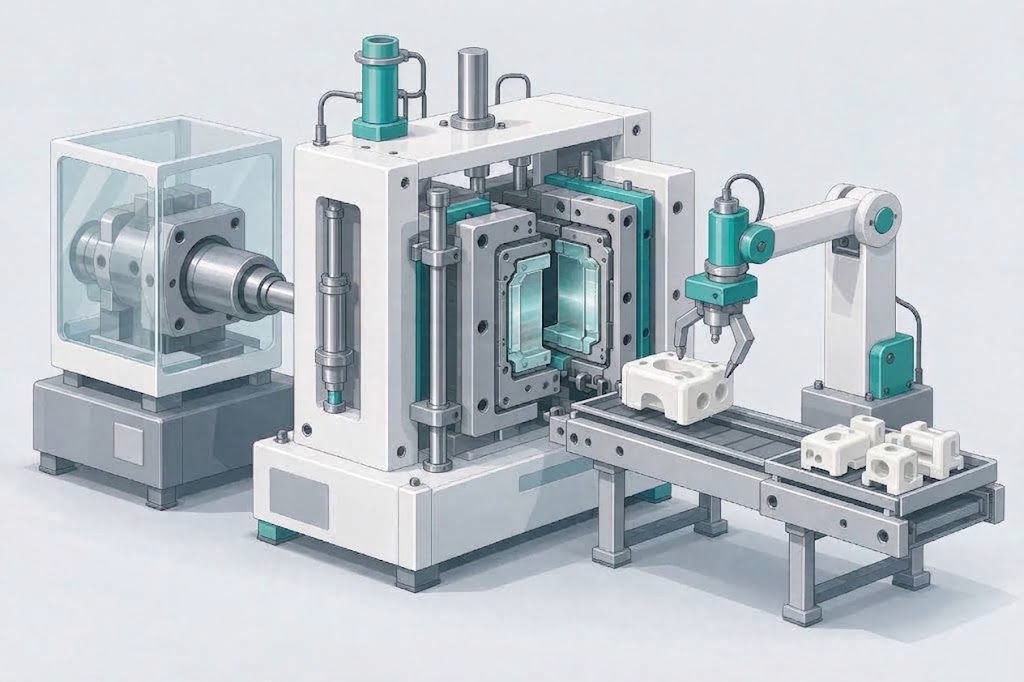
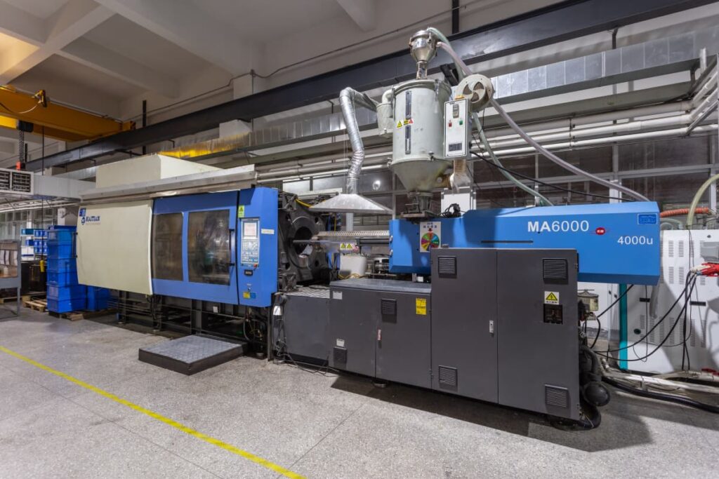
A single-cavity, single-machine setup keeps the process easy to control and audit. The sequence is the same whether loading is manual or robotic:
- Insert preparation. The insert is cleaned, deburred, and—when required—pre-heated. Cold steel or brass inserts act as heat sinks; pre-heating large metal inserts to roughly 150–200°C slows the thermal shock so plastic fills every knurl before freezing.
- Insert placement. The insert is seated on a locating pin, shut-off land, or magnetic core. Automated placement holds position to about ±0.05 mm; manual placement is typically ±0.10 mm.
- Mold close and injection. The machine injects molten plastic, commonly in the 200–300°C range depending on resin, at high pressure. Gate location is set so the flow front does not strike the insert head-on.
- Pack and cool. Holding pressure packs out the boss; cooling runs until the part can eject, often 15–30 seconds for a typical shot.
- Ejection and inspection. The part is stripped with the insert permanently captured. First articles go through a T1 sample evaluation before the tool is released.
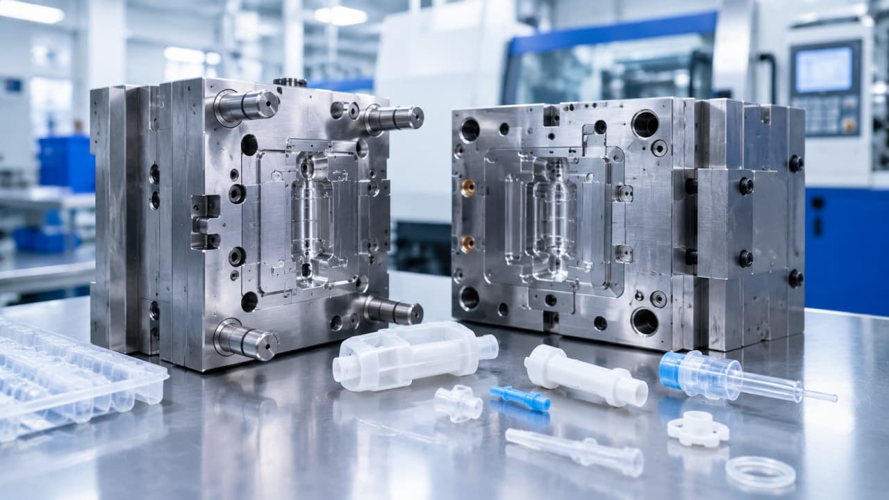
The basic structure of the mold that makes this possible—cavity, core, ejector, and shut-off—is explained in our overview of what an injection mold is.
Insert Molding Design Rules That Prevent Failure
Most insert molding failures are design failures, not process failures. The mold and machine can compensate for some weak designs, but not reliably. These rules address the majority of first-article problems before steel is cut.
Wall thickness around the insert. Keep a minimum plastic wall of 0.8 mm around a cylindrical metal insert; 1.2–2.0 mm is strongly preferred. As plastic cools around metal, thermal contraction creates hoop stress on the boss wall. For a 6 mm brass insert in PA66, a 1.0 mm wall holds static loads but cracks under repeated torque cycling above about 1.5 N·m, while a 1.5 mm wall raises the safe cyclic limit to roughly 3.5 N·m.
Boss outer diameter. Size the boss at least 1.5× the insert outer diameter—2× is a common starting point—so the plastic contains the full knurl depth plus a minimum wall. Smaller bosses concentrate hoop stress on a smaller cross-section and crack more readily, especially in glass-filled materials.
Insert surface features. Knurl, groove, or undercut the insert; never leave it smooth. A smooth cylinder relies only on compressive grip from plastic shrinkage, which is insufficient for most service loads. Diamond knurls 0.2–0.4 mm deep raise pull-out force roughly 3–5× over a smooth insert—about 3.5–4.5 kN in PA66 for a 6 mm insert versus 0.8–1.1 kN smooth. Annular grooves (≥1 mm wide, ≥0.3 mm deep) add an axial lock independent of the knurl; chamfers of 30–45° on the insert tip aid robotic loading.
Draft and corners. Apply 1–2° draft on plastic features parallel to the draw direction, and a minimum 0.5 mm radius on internal corners to avoid stress concentrations that invite cracking.
Gate placement. Keep the gate at least 3× the wall thickness from the nearest insert edge, and never gate directly at the insert face. A high-velocity jet deflects small inserts, causing dimensional error or flash. If geometry forces a near gate, use a sub-gate entering below the insert centerline so flow contacts the side, not head-on.
Venting and cooling. Vent 0.01–0.02 mm at end-of-fill zones near insert features so trapped air does not burn the knurl channels or leave a weak weld line behind the insert. Balance cooling channels because metal inserts pull heat faster than plastic and can cause thermal warping. Tighter DFM detail on bosses is in our guide to designing ribs and bosses, parting lines in the parting line guide, and achievable numbers in the injection molding tolerances reference.
| Design rule | Recommended value | Failure if ignored |
|---|---|---|
| Wall around insert | 1.2–2.0 mm (min 0.8 mm) | Hoop-stress cracking on cooling or cycling |
| Boss OD | ≥1.5× insert OD (2× typical) | Concentrated stress, sidewall fracture |
| Knurl depth | 0.2–0.4 mm diamond | Pull-out under torque |
| Draft | 1–2° | Scraping, insert displacement on ejection |
| Gate distance | ≥3× wall from insert edge | Insert shift, flash, weak weld line |
| Vent depth | 0.01–0.02 mm at end-of-fill | Burn marks, incomplete knurl fill |
*Values are industry-rule-of-thumb starting points; confirm exact dimensions with your molder against the resin datasheet and part load case.*
Material Pairing: Insert and Plastic Compatibility
Metal and plastic do not form a chemical bond in insert molding—mechanical interlock does the holding. Material choice therefore governs two things: whether the plastic wets and fills the insert features, and whether thermal expansion mismatch cracks the boss during cooling or in service.
Brass (free-machining grades such as C36000 and C37700) is the most common insert for threaded connections because its coefficient of thermal expansion (CTE) sits closer to engineering plastics than stainless does, reducing interface stress in cyclic service. Stainless steel (e.g., 316L) and aluminum are chosen for corrosion resistance or weight, but their larger CTE delta versus plastic demands thicker walls and sometimes pre-heat. Ceramic withstands temperature extremes that degrade metal but is brittle, so gate placement matters.
A practical compatibility check: pull the CTE of the resin from its datasheet, compare it with the insert CTE, and flag any pair with a delta above about 15 µm/m·°C for a stress simulation before tooling. Common pairings:
| Insert material | Works well with | Typical application | Watch-out |
|---|---|---|---|
| Brass (C36000/C37700) | PA, PBT, PPS, ABS | Threaded bushings, connectors | Minimize lead-content restrictions for some markets |
| Stainless 316L | PEEK, PC, PSU, PPS | Medical, sterile parts | Larger CTE delta; pre-heat and wall margin |
| Aluminum | PA, PC | Lightweight structural | No chemical bond; needs mechanical lock |
| Ceramic | High-temp resins | Sensor, electrical | Brittle; careful gating |
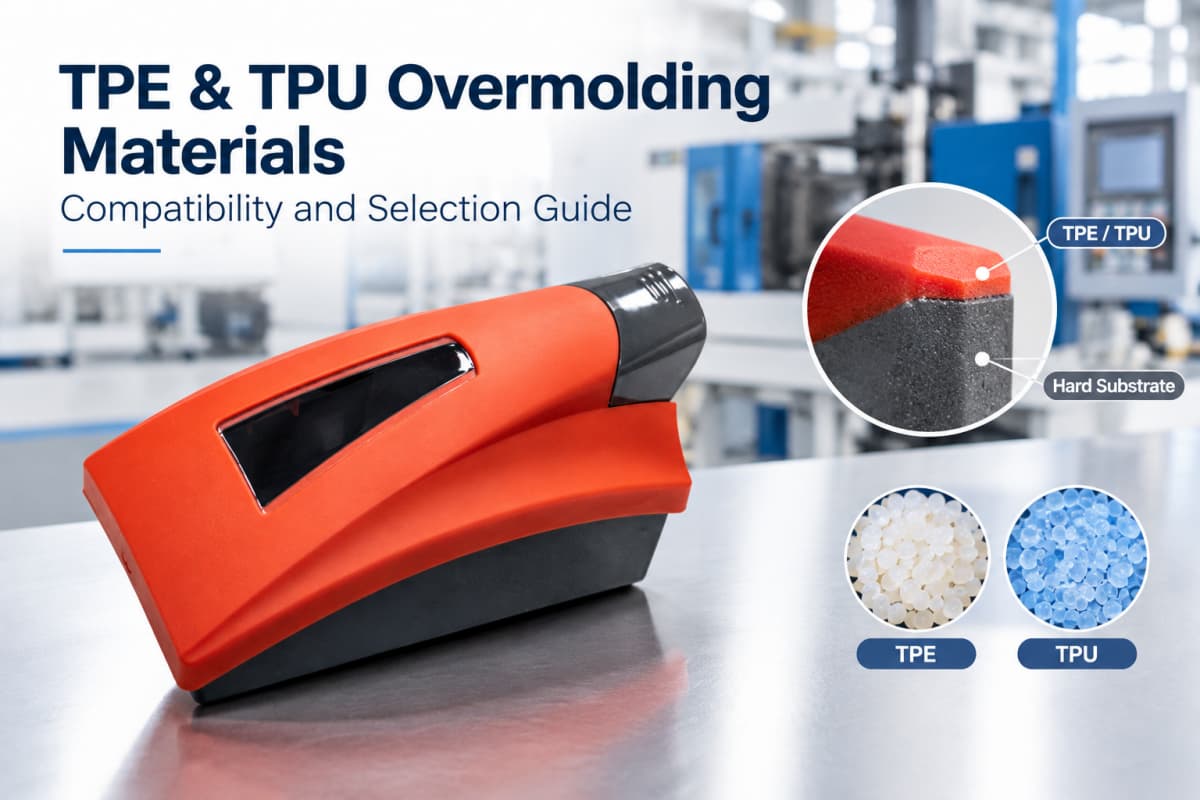
Soft-material overmolding pairings are a different problem and are covered in our TPE and TPU overmolding materials guide. For medical-grade selections, see our medical injection molding materials guide.
Common Insert Molding Defects and Root Causes
When an insert-molded part fails, the symptom points to a specific cause. Use this map to decide whether the fix is process, design, or material.
| Symptom | Likely root cause | First fix |
|---|---|---|
| Insert shifted or tilted | Gate jetting at insert, weak locator pin, thin-wall insert | Relocate gate; enlarge locating pin; add support pin |
| Hoop-stress cracking | Wall too thin, sharp internal corner, CTE mismatch | Increase wall to 1.2 mm+; add corner radius |
| Voids / short encapsulation | Cold insert, trapped air, insufficient pack | Pre-heat insert; add vents; raise pack pressure |
| Flash at insert thread | Worn shut-off, oversized insert, no shut-off land | Re-cut shut-off; verify insert tolerance (±0.05 mm) |
| Weak weld line behind insert | Converging flow fronts, poor venting | Relocate gate; add vent; consider sequential fill |
| Pull-out under torque | Smooth insert, no knurl/groove | Add diamond knurl or annular groove |
Many of these overlap with general molding problems; our common injection molding defects prevention guide explains the shared root causes.
Tooling, Loading Method, and Cost Trade-offs
The loading method is the main cost lever. Manual placement suits low volumes (often cited as feasible below about 5,000 units per year) where tooling amortization still beats separate assembly. Automated robotic loading pays off as volume rises and becomes clearly advantageous when a part carries three or more inserts or needs multi-directional positioning, because it removes labor and placement variation.
Hot runner versus cold runner affects scrap and consistency: a hot runner holds melt temperature to the gate and eliminates sprue/runner waste, while a cold runner costs less up front but generates regrind. The trade-off is detailed in our hot runner versus cold runner guide.
Tool steel choice follows volume: aluminum or pre-hardened steel for prototypes (1,000–10,000 shots), P20 for medium runs (100,000+), and hardened H13/S7 for high-volume automated lines (1,000,000+ cycles). Insert molding accelerates tool wear at shut-off faces, so planned maintenance—cleaning cores, inspecting locators—is part of the cost picture.
| Decision | Choose when | Trade-off |
|---|---|---|
| Manual loading | Low volume, simple insert | Slower, ±0.10 mm placement |
| Robotic loading | ≥3 inserts, high volume | Higher tool/automation cost |
| Cold runner | Lower upfront cost | Runner scrap, regrind |
| Hot runner | Consistent melt, less waste | Higher tool cost |
| Prototype steel | Validate first | Limited cycles |
*Cost ranges depend on part complexity, cavities, and region; request a quote rather than assuming a number.*
When Insert Molding Beats Overmolding and Two-Shot
Use insert molding when a precision metal or ceramic feature must be permanently captured and post-assembly would add joints, fasteners, or potting. It wins on:
- Electrical isolation of busbars, sensor modules, and pins inside dielectric plastic—no manual potting.
- Threaded metal features that outlast plastic threads by 3–5× in pull-out.
- Sealing a barrier around a fixed metal element without a gasket.
- Lightweighting by localizing metal only where load demands it.
Choose overmolding instead when the value is a soft, bonded skin on a plastic substrate, and two-shot when you need two plastics in one cycle at high volume and can justify the machine and tool investment. The two comparison articles—insert versus overmolding and two-shot versus overmolding—walk through the decision in detail.
Insert Molding for Medical and Regulated Parts
Medical parts favor insert molding because it integrates a metal feature into a single sealed component with no loose fasteners that could work free in a sterile field. Surgical handles, connector contacts, catheter marker bands, and drug-delivery housings commonly use it. Regulated programs add process validation (IQ/OQ/PQ under ISO 13485) and biocompatibility evidence for the materials in contact with tissue or fluid.
This is a deep enough topic to warrant its own guide—see our medical device injection molding guide and the dedicated ISO 13485 medical molding guide.
FAQ
Is insert molding stronger than a press-in insert? Yes for retained load. Plastic shrinks onto diamond knurls and grooves, giving 3–5× the pull-out of a smooth press-fit and far better torque resistance, because the interlock engages across the full knurl depth rather than surface friction alone.
Can you insert mold PEEK? Yes. PEEK is used for medical and high-temperature inserts, often with stainless 316L, but its high melt and CTE behavior demand careful wall design, gating, and validation. Confirm sterilization and biocompatibility requirements with your molder.
What is the minimum practical batch for insert molding? Manual loading is commonly viable below about 5,000 units per year when it avoids a separate assembly step; automated loading suits higher volumes. The economic breakpoint depends on insert count and assembly cost, not a fixed number.
Why does my insert-molded boss crack after assembly? Almost always thin wall or a sharp corner combined with CTE mismatch. Raise the wall to at least 1.2 mm, add a 0.5 mm corner radius, and check the resin-to-insert CTE delta.
Do I need a hot runner for insert molding? Not always. Cold runners work for many programs; hot runners help at high volume by cutting scrap and holding melt temperature. See the runner comparison.
Talk to Our Insert Molding Technical Team
Have an insert-molded part in development? Send us your 3D CAD, insert drawing, resin preference or performance target, annual volume, and any regulatory requirements. Our engineering team will review wall thickness, boss OD, gate location, insert retention features, material pairing, venting/cooling, and loading/tooling strategy. You’ll get a practical DFM review and a clear recommendation—insert molding, overmolding, or two-shot molding—plus a quote or sample plan if the project is a fit.