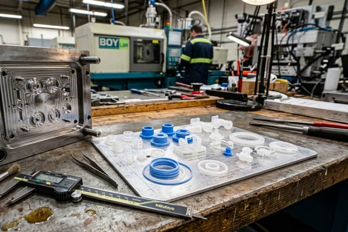

Medical injection molding is no longer a price-per-part comparison. The suppliers winning medical programs in 2026 are being judged on validation evidence, material capability, tolerance strategy, and change control as much as on unit cost — and the FDA’s Quality Management System Regulation, effective 2 February 2026, has pushed ISO 13485:2016 into the regulatory baseline for devices sold in the United States.
That shift changes what you should ask for, and when you should ask for it. This guide covers six changes now affecting medical device injection molding programs, what each one means for a device manufacturer’s tooling, material, and supplier decisions, and how to convert them into a supplier evaluation checklist you can use before you release a purchase order.

What Is Actually Changing in Medical Injection Molding — The Short Answer
The core change is that the manufacturing process is now part of the regulated product. Regulators and notified bodies expect a medical device manufacturer to demonstrate control over how a plastic component was made, not only that the finished component passed inspection. As a consequence, suppliers are being evaluated on process evidence — validated windows, traceable resin lots, in-process data, and formal change control — because without that evidence the device manufacturer carries the risk at audit and in the field.
Six shifts follow from that single change:
| # | Shift | What it changes for you |
|---|---|---|
| 1 | Validation evidence is requested at quotation stage | RFQ templates need to include validation, traceability and change-control deliverables |
| 2 | Material choice splits into high-performance resins and multi-material parts | Resin grade, bio-compatibility route and multi-shot capability become selection criteria |
| 3 | Tooling splits into bridge tooling and production tooling | Two capital decisions instead of one, with different documentation requirements |
| 4 | Miniaturization changes tolerance strategy | Tolerances must be set against part size and the metrology actually available |
| 5 | Quality moves from end-of-line inspection to in-process data | Evidence shifts from inspection reports to process capability and monitoring records |
| 6 | Manufacturing footprint becomes an engineering decision | Dual sourcing, tool ownership and audit access enter the technical evaluation |
A supplier that can produce good parts but cannot produce the evidence behind them is a compliance risk, not a cost saving. This is why ISO 13485 injection molding has moved from a marketing credential to a working requirement in supplier selection.
Trend 1 — Validation Evidence Has Moved From the Audit to the RFQ
The short answer: process validation documentation is now requested before tooling is released, because a validated process window has to be built during development, not reconstructed after an audit finding.
Process validation for medical molding is usually structured as IQ (installation qualification), OQ (operational qualification) and PQ (performance qualification). IQ confirms the machine and auxiliary equipment are installed and functioning as specified. OQ establishes the process window — the combinations of melt temperature, mold temperature, injection speed, packing pressure and cooling time that produce conforming parts. PQ demonstrates that the process, run within that window, consistently produces conforming parts across a meaningful production run.
The practical consequence for device manufacturers is that the supplier must be able to run and document a design-of-experiments or similar structured study, not simply hand over a “golden” parameter sheet. If your supplier’s response to a validation request is a single parameter set with no window, the process has no documented tolerance for normal variation — and any drift becomes an unplanned deviation.

| Document / deliverable | Why you need it | When to request it | Risk if missing |
|---|---|---|---|
| Validation plan and protocol (IQ/OQ/PQ outline) | Confirms the supplier has a method, not just an intention | With the quotation or before tooling release | Validation rework late in design transfer |
| Process window study (OQ data) | Proves the process tolerates normal variation | After T1 samples, before PQ | Undocumented drift, unexplained out-of-spec parts |
| Resin lot traceability records | Links finished components back to incoming material | With each production lot | No recall containment, failed audit trail |
| Change control procedure | Defines what must be re-validated after a change | During supplier qualification | Unauthorized mold, resin or process changes |
| Measurement system analysis (gauge R&R) | Shows the measurement itself is trustworthy | Before capability claims are accepted | Capability data that does not reflect the part |
| Batch records and inspection data | Evidence the validated state was maintained | On request and per your quality agreement | Unverifiable production history |
ISO 13485 Is No Longer a Differentiator — It Is the Baseline
For manufacturers selling into the United States, the regulatory floor moved on 2 February 2026. The FDA’s Quality Management System Regulation (QMSR) amended 21 CFR Part 820 and incorporates ISO 13485:2016 by reference, with FDA-specific additions retained. The agency also retired the Quality System Inspection Technique and moved to the inspection process described in Compliance Program 7382.850.
Two consequences matter to a device manufacturer choosing a molding partner. First, records that were previously outside routine FDA review — management reviews, internal audit reports and supplier audit reports — are now inspectable. Second, an ISO 13485 certificate does not by itself establish QMSR compliance; the FDA retains its own requirements and its own inspection authority. A molding supplier whose quality system operates as a documented, auditable system — rather than a certificate on a wall — is materially easier to include in your own QMS.
GoodTech operates a documented medical molding quality management system built around incoming, in-process and final quality control, with material traceability from resin batch to finished component.
What to Ask For Before You Send a Purchase Order
- A validation plan that names the responsible parties, the acceptance criteria and the sampling rationale.
- The process window study format, including which parameters are treated as critical.
- The change control procedure, with explicit rules on what triggers re-validation.
- Resin traceability records and the format in which they will be supplied.
- The measurement strategy, including the metrology method for each critical dimension and gauge R&R evidence.
- The quality agreement template, including deviation notification and CAPA expectations.
Trend 2 — Material Choice Is Splitting Into High-Performance Resins and Multi-Material Parts
The short answer: material selection is being driven less by mechanical strength alone and more by the sterilization method, the biological evaluation route, and whether the device needs more than one material in a single part.
Medical molding has historically started from commodity resins — ABS, PS, PE and PP — because they process predictably and cost less. That remains valid for many housings and non-critical components. What has changed is that more designs now specify engineering and high-performance resins because the part must survive autoclave or chemical sterilization, hold dimensions at elevated temperature, or meet a biological evaluation requirement that a commodity grade cannot support.
Resin families commonly used in medical molding include PC, PBT, POM, PA, PPS, PC+PBT blends, PSU/PPSU and PEEK, alongside the commodity grades. Glass-fiber and glass-bead reinforced compounds are used where stiffness or dimensional stability matters more than surface appearance. The specific grade, additive package and regulatory status of the compound — including whether it carries a USP Class VI or ISO 10993-1 testing history — are properties of the resin supplied by the resin manufacturer, and they should be confirmed in writing with the resin supplier, not assumed from the polymer family name.

| Material family | Typical medical use | Why it is chosen | Confirm before ordering |
|---|---|---|---|
| PC | Housings, luer components, transparent covers | Clarity, toughness, dimensional stability | Sterilization method tolerance; chemical compatibility |
| PBT / PBT blends | Connectors, structural internals | Chemical resistance, stable molding | Grade’s sterilization and biological status |
| POM | Precision mechanical parts, gears, latches | Low friction, tight-tolerance molding | Sizing and tolerance behavior; sterilization route |
| PA (incl. reinforced) | Structural brackets, fluid-path parts | Stiffness, wear resistance | Moisture uptake; dimensional change after conditioning |
| PPS | Autoclave-exposed parts, fluid contact | High temperature and chemical resistance | Required mold temperatures and tool steel selection |
| PSU / PPSU | Reusable instrument components | Repeated steam sterilization | Cost against the sterilization cycles actually required |
| PEEK | High-performance implants and instrument parts | Mechanical performance, chemical resistance | Grade, regulatory route and processing parameters |
| ABS / PS / PE / PP | Disposable housings, trays, non-critical parts | Cost, predictable processing | Whether the biological evaluation route needs a higher grade |
For a structured comparison of resin behavior and processing windows, see the engineering plastics for injection moulding guide.
Engineering Resins Replacing Commodity Plastics
The trade-off is not “better material, higher price.” It is a trade between sterilization cycles required, dimensional stability across those cycles, and processing difficulty.
Engineering resins are the right call when the part must retain dimensions after repeated steam sterilization, when it sits in continuous fluid contact, when it must function at elevated temperature, or when a biological evaluation route requires documented material history. They are the wrong call when a disposable housing has no sterilization exposure and the design is dominated by cost — a higher-grade resin adds cost and frequently narrows the processing window without changing the device’s regulatory path.
Two practical checks prevent most material surprises:
- Confirm the sterilization method before the resin is frozen. A material acceptable for ethylene oxide may not be acceptable for repeated autoclave exposure at the device’s geometry and wall thickness.
- Confirm the biological evaluation route with the resin supplier. Whether a grade has relevant USP Class VI or ISO 10993-1 supporting data is a supplier statement, and it should be documented rather than inferred.
Two-Shot Molding and Overmolding for Sealing and Soft-Touch Interfaces
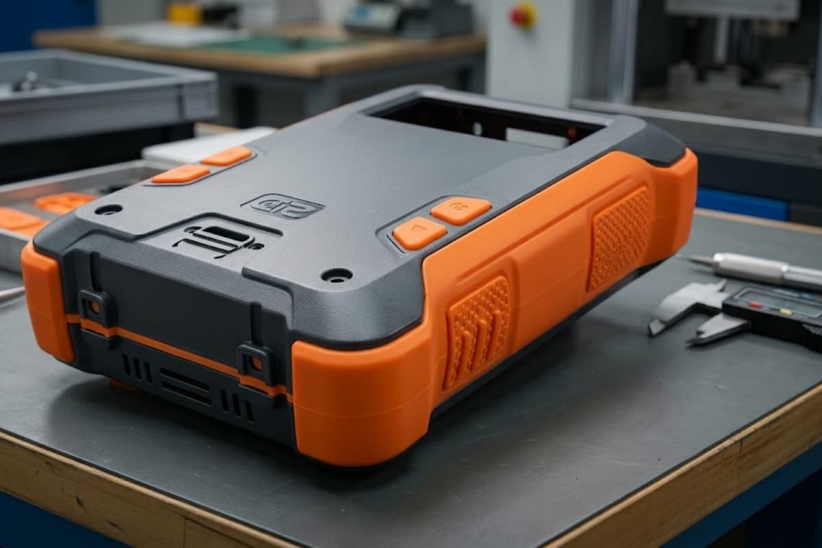
Multi-material parts have become more common because they remove an assembly step and eliminate a bond line. Two-shot molding produces a rigid substrate and an elastomeric or second-color element in one machine cycle; overmolding achieves a similar result when the substrate is inserted rather than molded in the same tool.
The decision usually comes down to volume, sealing requirement and material compatibility.
| Situation | More suitable approach | Reason |
|---|---|---|
| High annual volume, two materials combined every cycle | Two-shot molding | One cycle, no manual substrate handling, consistent bond |
| Insert is metal, a pre-made component, or low volume | Overmolding / insert molding | Avoids a second molding station and dedicated second-shot tooling |
| Soft-touch grip or ergonomic surface on a rigid body | Two-shot or overmolding | Eliminates adhesive or mechanical assembly |
| Fluid-tight seal where the bond line is a leak risk | Two-shot, with material compatibility confirmed | A single-cycle bond removes a separate sealing interface |
| Low volume or unproven design | Single-material part with a separate gasket | Lower tooling investment while the design is still changing |
The governing constraint is chemical compatibility between the two materials. Not every rigid/elastomer pair will bond, and the pair that bonds may not survive the sterilization method. The choice between insert moulding vs overmoulding should therefore be made after the material pair and the sterilization route are both confirmed, not before.
Trend 3 — Tooling Strategy Is Splitting Into Bridge Tooling and Production Tooling
The short answer: more programs now buy two tools instead of one — a bridge tool to validate the design and supply clinical or verification builds, and a production tool specified once the design is frozen.
This split exists because design changes are cheap in tooling and expensive in validated processes. Cutting a production tool before the design is stable means either absorbing tool modifications after validation or restarting validation after a tool change. Bridge tooling decouples the two.

| Program stage | Suitable tooling approach | Main trade-off |
|---|---|---|
| Concept and feasibility | CNC machined or 3D-printed prototypes | Speed and geometry freedom against material representativeness |
| Design verification, clinical builds | Bridge tooling (often aluminium or lower-cavitation steel) | Faster lead time and lower investment against tool life and process similarity |
| Design freeze, scale-up | Production tool (specified cavitation, steel grade, runner and cooling) | Higher investment against validated, repeatable output |
| Mature high-volume production | Production tool with multi-cavity, hot runner, optimized cooling | Higher tooling cost against cycle time and unit cost |
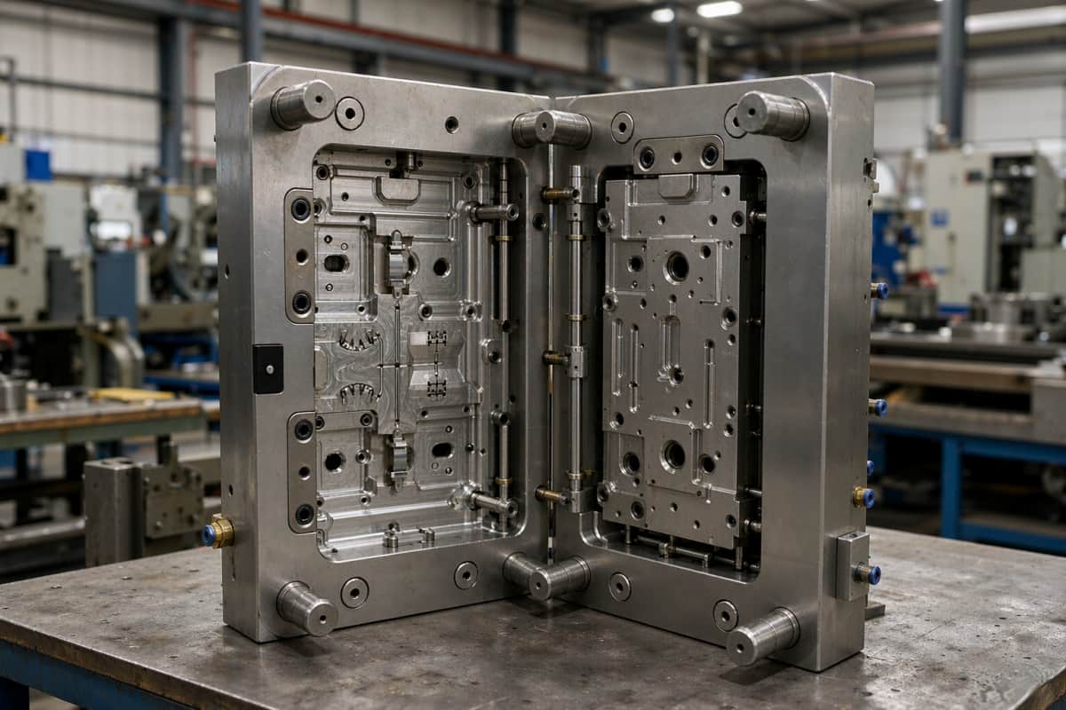
Tool fabrication itself remains the schedule driver in most programs. GoodTech’s plastic mold fabrication capability covers cold runner, hot runner, conformal cooling and high-polish or textured finishes, with mold flow analysis and tooling design feeding into the DFM stage.
Bridge Tooling for Design Verification and Clinical Builds
Bridge tooling is judged on different criteria than production tooling. Tool life matters less than the ability to produce parts that represent the final process closely enough for design verification and clinical evaluation. Aluminium tooling is frequently chosen here because it machines faster and costs less; the trade-off is reduced tool life, different cooling behavior, and a process that does not transfer one-to-one to a steel production tool. The aluminium vs steel moulds for rapid tooling comparison sets out where that trade-off is acceptable and where it is not.
What to confirm for bridge tooling:
- Whether the bridge tool will run the same resin as the production tool, or a substitute.
- Whether the bridge tool’s gate location and cooling layout will match the production tool closely enough for dimensional comparison.
- What documentation you will receive, since the parts may support design verification records.
Production Tool Decisions That Are Hard to Reverse Later
Four production-tool decisions are expensive to change after validation:
- Cavitation. Adding cavities later is a new tool, not a modification. Cavitation should be set against annual volume, cycle time and the tolerance capability demonstrated on the bridge tool.
- Runner system. Hot runner vs cold runner affects material waste, cycle time, color-change flexibility and gate vestige. Hot runner systems from established suppliers reduce the risk of thermal imbalance across cavities; the added complexity has to be justified by volume.
- Cooling design. Conformal cooling can shorten cycle time and reduce warpage, but it adds tooling cost and complexity. It pays back where cycle time dominates unit cost or where warpage is the limiting quality issue.
- Steel grade and mold class. For medical parts requiring long production life without dimensional drift, tool steel selection and corrosion resistance matter — particularly for resins processed at high melt temperature or aggressive sterilization chemistry. The mold class you specify should be tied to the total production volume you actually expect, including any planned line extensions.
Trend 4 — Miniaturization Changes How Tolerances Are Set
The short answer: as part dimensions shrink, tolerances can no longer be scaled down from larger parts — they must be set against the molding process limits and against the measurement method that will actually be used.
Medical molding routinely spans a very wide size range; GoodTech’s production range, for example, covers parts from 0.2 g to 4,500 g. At the small end, several constraints change at once. Gates and runners become small enough that shear and fill behavior dominate the process window. Ejection forces need to be balanced against delicate geometry. Wall thickness variation becomes a larger proportion of the nominal dimension. And the metrology that worked for a large housing — a touch probe on a CMM, for instance — may not resolve the features of a micro-molded part, which pushes the measurement toward optical systems.
The practical consequence is that a tolerance stack inherited from a larger device should be re-examined rather than applied. A tolerance that is achievable on a 200 g housing may be outside the process capability of a 0.2 g component, while a tolerance that looks loose on the small part may be the correct process limit.

| Feature type | Common approach | What to check |
|---|---|---|
| Overall dimensions on a small part | Set against demonstrated process capability | Whether the supplier has capability data at that size, not interpolated |
| Mating and sealing features | Tight, but limited to functional surfaces | Which dimensions genuinely affect function |
| Features created by the tool (gate vestige, ejector marks) | Defined by tooling, not by tolerance call-out | Tool design and finishing, not tighter tolerances |
| Optical or light-guide features | Dominated by polish and material | Surface finish spec and resin clarity |
| Micro features on micro parts | Must match available metrology | Whether the measurement method can resolve the feature |
Setting tolerances that the process and the metrology cannot actually hold is one of the most common sources of late-stage cost. The injection moulding tolerances guide covers how to set limits that are both realistic and cost-effective.
Trend 5 — Quality Control Is Shifting From End-of-Line Inspection to In-Process Data
The short answer: end-of-line inspection can only tell you whether a lot is bad; in-process data tells you whether the process is drifting while there is still time to correct it.
Medical molding quality control is typically organized as incoming quality control (resin certificate of analysis, moisture content, correct grade and lot), in-process quality control (dimensional and visual checks against a control plan), and final quality control (dimensional, functional and appearance verification). The change is not that final inspection has disappeared — it is that the weight of evidence has moved toward the in-process layer.
| Control approach | What it detects | What it cannot detect |
|---|---|---|
| Final inspection, AQL sampling | Whether a completed lot meets specification at sampled points | Drift between samples; the cause of a defect |
| In-process dimensional checks | Trends against critical dimensions during the run | Measurement system error unless gauge studies are done |
| Process monitoring (pressure, temperature, cycle) | Departure from the validated window in real time | Whether the parts produced during the excursion are conforming |
| In-line vision or weight verification | Gross dimensional and fill-related defects at 100% coverage | Internal or functional defects |
| Statistical process capability reporting | Whether the process is capable and stable over time | Capability on dimensions not included in the study |
For device manufacturers, the practical implication is about the form of the evidence you ask for. A certificate of conformance stating “parts meet specification” transfers almost no information. A capability report on the critical dimensions, tied to the validated process window and produced from in-process measurement, tells you whether the process is under control — and gives you something defensible in your own design history or batch records.
What to ask for:
- The control plan, naming the features measured, frequency, method and acceptance criteria.
- Capability data on critical dimensions, with the measurement method and gauge study behind it.
- Process monitoring parameters and alarm limits, and the reaction plan when a limit is exceeded.
- The metrology list, so you know which dimensions are measured on a CMM, optically, or by functional gauge. GoodTech’s metrology and inspection equipment covers coordinate measurement, optical comparison, color verification and automated vision.
- The CAPA process and what triggers it.
Trend 6 — Manufacturing Footprint Has Become an Engineering Decision
The short answer: where a part is molded now affects the validated process, the audit trail and the total cost — so the decision belongs with engineering and quality, not only with procurement.
Medical molding supply is increasingly evaluated as a footprint question rather than a factory question. Dual-base suppliers — engineering and program management close to the customer, manufacturing in a lower-cost region — are common because they shorten the communication loop without giving up the manufacturing economics. GoodTech, for example, operates from Chicago and Shenzhen, with its main manufacturing site in China and an additional site in Vietnam.
There is a real trade-off to evaluate, and it is not automatically resolved in favour of the lowest labour cost.
| Cost / risk factor | Single regional supplier | Dual-base supplier (local engineering, offshore manufacturing) |
|---|---|---|
| Unit price | Usually higher | Usually lower |
| Time to resolve an engineering question | Shorter, fewer handoffs | Depends on whether the local team holds engineering authority |
| Tooling ownership and transferability | Straightforward | Requires explicit tool ownership and transfer terms |
| Audit access | Usually straightforward | Requires documented audit rights at the manufacturing site |
| Supply continuity | Single point of failure | Contingency if the second site is genuinely qualified |
| Tariff and freight exposure | Determined by origin | Depends on the site the tool actually runs in |
| Change control across sites | Simpler | Requires site-specific control and re-validation rules |
Two points determine whether a dual-base model helps or hurts. First, whether the customer-facing engineering team has the authority and capability to make DFM and process decisions, or whether every technical question is relayed to a distant plant. Second, whether the quality system controls each manufacturing site independently, with site-specific validation and change control. A supplier that can answer technical questions within a working day — because one engineering team closes the loop while the other is offline — reduces the schedule risk that usually accompanies offshore tooling. Practical guidance on the commercial and quality mechanics is covered in working with a China supplier.
How to Turn These Trends Into Supplier Selection Criteria
The six trends above converge on a small number of questions that separate suppliers capable of supporting a regulated medical program from suppliers who can only mold parts. For a broader framework, see the 10 key criteria for medical device contract manufacturers.
Engineering Support and DFM Input
Engineering-driven suppliers review the design before quoting. A DFM review should identify wall thickness problems, ribs and bosses that will sink or warp, gate locations that will trap material or leave visible vestiges, draft angles that will cause dragging, and tolerance call-outs that the process cannot hold. The value is not the review document itself — it is whether the feedback arrives early enough to change the design at no cost. The DFM design guide sets out the review criteria a medical program should expect, and rapid prototyping is often the cheapest way to test a DFM conclusion before cutting a tool.
IP Protection and NDA Practice
For device manufacturers, CAD files, tooling designs and resin specifications are the core intellectual property, and a component supplier frequently sees all three. The practical test is not whether a supplier will sign an NDA — almost all will — but whether confidentiality is operational rather than a document. Ask how drawings are stored and who can access them, who holds the physical tool and under what terms, what happens to tool ownership and data at the end of the program, and whether the supplier will accept your NDA template or insists on its own. GoodTech works under NDA on customer tooling and design data as a standard condition of medical programs.
Cross-Cultural Communication and Response Time
Cross-cultural communication is not a soft criterion in offshore medical molding; it is a schedule and quality variable. A misread drawing note, an unconfirmed resin substitution, or a tolerance assumed rather than clarified turns into a deviation. The measurable version of this criterion is the response loop: how quickly a technical question receives a substantive engineering answer, whether the answer comes from an engineer or a sales contact, and whether the supplier volunteers a problem before you discover it. In GoodTech’s model, US-based engineers support customers in the United States while Shenzhen-based engineers run the manufacturing process, which gives a working-day turnaround across the time difference.
Speed to First Samples and Program Turnover
Fast turnover should be evaluated as a capability with conditions attached, not as a promise. The factors that actually determine how quickly a program reaches validated production are the completeness of the input data, how early DFM feedback arrives, whether the tooling approach matches the program stage, and how much validation scope the regulatory route requires. A supplier that compresses tooling fabrication while leaving validation to the end has not compressed the program — it has moved the risk. What to ask: what the tooling fabrication schedule assumes, what the first-article inspection and T1 evaluation will cover, and who signs off on design freeze. The T1 sample evaluation guide describes how that evaluation should be structured.
GoodTech’s production capacity supports more than 60 molds per month and more than 15 million plastic parts per month across 45 molding machines from 60 to 1,000 tons, which is the kind of capacity that allows a bridge tool and a production tool to be developed in parallel rather than sequentially.
Medical Molding Supplier Checklist
| Evaluation area | A strong answer looks like | Warning signal |
|---|---|---|
| Validation | Named protocol, documented process window, defined re-validation triggers | “We have ISO 13485” with no validation plan |
| Material control | Resin lot traceability, supplier certificates, grade confirmation in writing | Accepts a resin family name without grade confirmation |
| DFM | Written review returned before quotation, with specific geometry feedback | Quotation issued with no design feedback |
| Tolerance strategy | Capability data at comparable part size; tolerances negotiated | Accepts every tolerance without comment |
| Quality evidence | Control plan, capability reports, gauge studies, defined CAPA trigger | Certificates of conformance as the only evidence |
| Tooling ownership | Explicit ownership, transfer and end-of-program terms | Ownership left undefined in the agreement |
| IP protection | Operationally enforced access control; accepts customer NDA template | Unwilling to put tool ownership in writing |
| Communication | Technical answers from engineers within a working day | Quotes-only responses, or answers routed through sales |
| Footprint | Site-specific validation and change control; audit access defined | Multiple sites with one undifferentiated quality claim |
Common Mistakes That Cost Device Manufacturers Time and Money
| Mistake | Consequence | How to avoid it |
|---|---|---|
| Cutting the production tool before the design is frozen | Tool modification after validation, or re-validation | Use bridge tooling for design verification and clinical builds |
| Accepting tolerances without checking capability | Chronic yield loss or an impossible inspection requirement | Request capability data at comparable part size before freeze |
| Choosing the resin before the sterilization method is confirmed | Material substitution after validation, or field failures | Confirm sterilization route, then select and document the grade |
| Treating an ISO 13485 certificate as evidence of a working QMS | Audit findings that land on the device manufacturer | Review the control plan, traceability records and CAPA process |
| Leaving tool ownership and access undefined | Disputed tool access at the end of the program | Put tool ownership, transfer and end-of-life terms in the agreement |
| Selecting on unit price alone | Total cost rises through tooling, validation and containment | Evaluate unit cost together with tooling, validation and freight |
| Not defining what triggers re-validation | Uncontrolled change, and evidence that no longer applies | Agree re-validation triggers in the quality agreement |
| Running a program with no local engineering authority | Technical questions take days to resolve | Confirm where DFM and process decisions are actually made |
Frequently Asked Questions
What is medical injection molding?
Medical injection molding is the injection molding of plastic components for medical devices and diagnostic equipment, produced under a quality management system that supports regulatory requirements such as ISO 13485:2016. The difference from general injection molding is not the molding machine but the evidence around it: validated processes, traceable materials, defined change control, and inspection data tied to a control plan.
How is medical injection molding different from standard injection molding?
The molding physics are the same. What differs is documentation and control. Medical molding requires a validated process window, material traceability from resin lot to finished component, formal change control with defined re-validation triggers, and quality records that a device manufacturer can reference in its own quality system. Standard commercial molding often provides equivalent parts with far less of that evidence.
Which materials are used in medical injection molding?
Common choices include PC, PBT and PC+PBT blends, POM, PA, PPS, PSU or PPSU, and PEEK, alongside commodity resins such as ABS, PS, PE and PP for non-critical or disposable parts. Glass-fiber and glass-bead reinforced compounds are used where stiffness or dimensional stability matters. Whether a particular grade has supporting data for a biological evaluation route — for example USP Class VI or ISO 10993-1 — is a property of the specific resin from the specific resin manufacturer and should be confirmed in writing rather than assumed.
Does medical injection molding require ISO 13485?
The supplier is not always required to hold ISO 13485 certification, but the device manufacturer must be able to demonstrate control of the process, which in practice means the molding supplier operates within a compliant quality system. Since 2 February 2026, the FDA’s Quality Management System Regulation has incorporated ISO 13485:2016 by reference into 21 CFR Part 820 for devices marketed in the United States, and ISO 13485 certification alone does not establish QMSR compliance. What matters is whether the system functions — procedures, records, reviews and audits that are actually performed and available for inspection.
How long does it take to get from design freeze to validated medical molding production?
There is no single answer, because the schedule is set by the completeness of the input data, the tooling approach, and the validation scope your regulatory route requires. A program that starts with a stable design, complete drawings and an early DFM review reaches first samples faster than one that revises geometry during tooling. Rather than asking for a headline lead time, ask the supplier to break the schedule into tooling fabrication, first-article inspection and T1 evaluation, and process validation, and to state what each stage assumes.
Can a molding supplier sign an NDA before receiving our CAD files?
Yes, and this should be a standard first step in a medical molding program. Before sharing drawings, agree the scope of confidential information, who may access it internally, how tooling ownership is recorded, and what happens to design data and tooling at the end of the program. A supplier that treats these points as routine is easier to audit and safer to work with than one that treats the NDA as a formality.
What is a bridge tool and why would we need one?
A bridge tool is a lower-investment mold used to produce parts for design verification, clinical builds or early market supply before the design is frozen. It typically uses aluminium or lower-cavitation steel and is faster to fabricate than a production tool. The benefit is that it decouples design iteration from validated production tooling, so the production tool is only cut once the design is stable.
Should we specify a hot runner or a cold runner for a medical part?
It depends on volume, material, color-change requirements and gate vestige acceptance. Hot runners reduce material waste and cycle time but add tooling complexity and thermal management requirements; cold runners are simpler and more flexible for low volume or frequent material changes. The hot runner vs cold runner comparison covers the decision factors in detail.
What to Do Next
The trends above do not change the goal of medical injection molding, but they change what a device manufacturer must verify before committing a program: a validated process, a traceable material supply chain, a tolerance strategy matched to the part and the metrology, evidence in the form of process data rather than inspection certificates, and a supplier whose engineering and quality systems work across whatever footprint the program uses.
A practical next step is to test these criteria against your current program rather than against a supplier’s brochure. Send us your part drawing, resin grade, annual volume, sterilization method and regulatory target — GoodTech will return a DFM review, an outline of the tooling approach (bridge or production), and a validation plan structure you can evaluate against your own quality system.